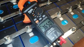
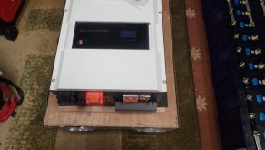
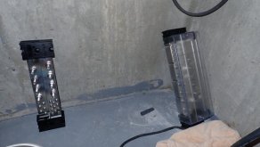
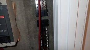
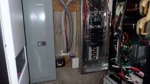
I think a couple of pictures will illustrate what I was trying to explain when I said use the front terminals on that 40 amp supply to set the voltage.
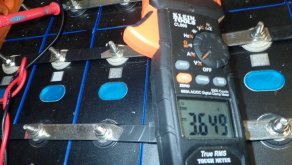
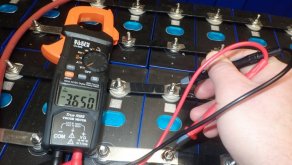
It's hard to see, so let me explain. The meter on the right is plugged directly into the two front jacks, and with no cell attached I set the voltage to 3.6 volts (or as close as it would let me). Now the pictures show with a cell attached and charging, when I first started the cell charging, I adjusted current to prevent it going over 40 amps. The meter on the left is attached directly to the battery terminals, and thus is reading the cell voltage. The closer the cell voltage gets to the set voltage (3.6 volts) the less current is flowing (that's normal, current is directly related to the voltage difference between the cell voltage on the left and the charging set voltage on the right). This is the safest method of charging a single cell, although a bit slower (takes about 8 hours instead of 7 for a 280AH cell). It is NOT the only method or approach. But as I pointed out, when charging a single cell, it takes about 9 minutes to go from 3.4 volts to 3.65 volts at 40 amps. Certainly for a large bank in parallel, that time will increase by the number of cells in parallel. It is entirely safe to charge a single cell or a large group of parallel cells using this method, you would have to ignore it for a day or two to substantially over charge either a cell or a large group in parallel (which is a big concern for me, I should have ordered a couple of spare cells). I then top each cell up individually to 3.65 on my Riden, usually about an amp hour or less (from 3.6 to 3.65).
Certainly if you watch things closely, you can crank up the set voltage to get 40 amps out of the charger as long as you want. But once it hits 3.4 volts, you really need to pay close attention to the cell voltage and not let it rise above 3.65. It is certainly not a bad approach to take for a large group of cells in parallel and will save time. For a single cell, you could even set a timer to remind you in 6 hours (assuming fully discharged 280AH cell) and then turn down the voltage. Not trying to criticize, just trying to let people without any experience know the safest way to charge without over charging.


")