Hedges
I See Electromagnetic Fields!
- Joined
- Mar 28, 2020
- Messages
- 20,600
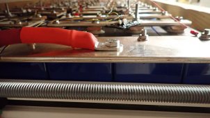
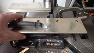
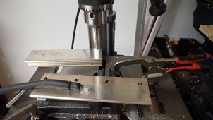
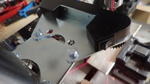
Instead of running the cable direcly to one battery terminal I thought it would be beneficail to add a second plate or tap this plate. I would add the battery connection so it would be in the center of the 3 inch plate. In the 3rd picture I would add the connection in the middle of that plate slightly forward.
If a 3" plate joins 4 cells at the end, it seems pretty well balanced. Two cables with their own bolts to the place between cells 1 & 2 and between 3 & 4 would be perfectly symmetric.
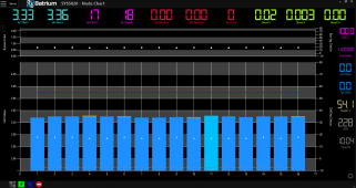
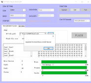
Interesting monitor boards, separate one for each cell. Are they powered by the local cell? Do they communicate to the next cell's board with a slight voltage offset, or all communicate on a bus as much as 48V away?
When I was top ballancing the batteries I moved it often as the cell directly connected to the charger increased faster. Since I have not watched a 4p16s charge up I'm just pondering ideas to achieve the best possible outcome.
So that was when parallel balancing a large number of cells all at once? Could be contact resistance, but I don't expect much between bolted electroplated copper bars (only contact to the cell). The final configuration should have very little problem. Unless one cell has poor contact, in which case three cells in the 4p get all the current.
 no response from seller yet, let me add another