diy solar

diy solar

Very new to solar but started purchasing items, not sure of the final specs of the whole system.

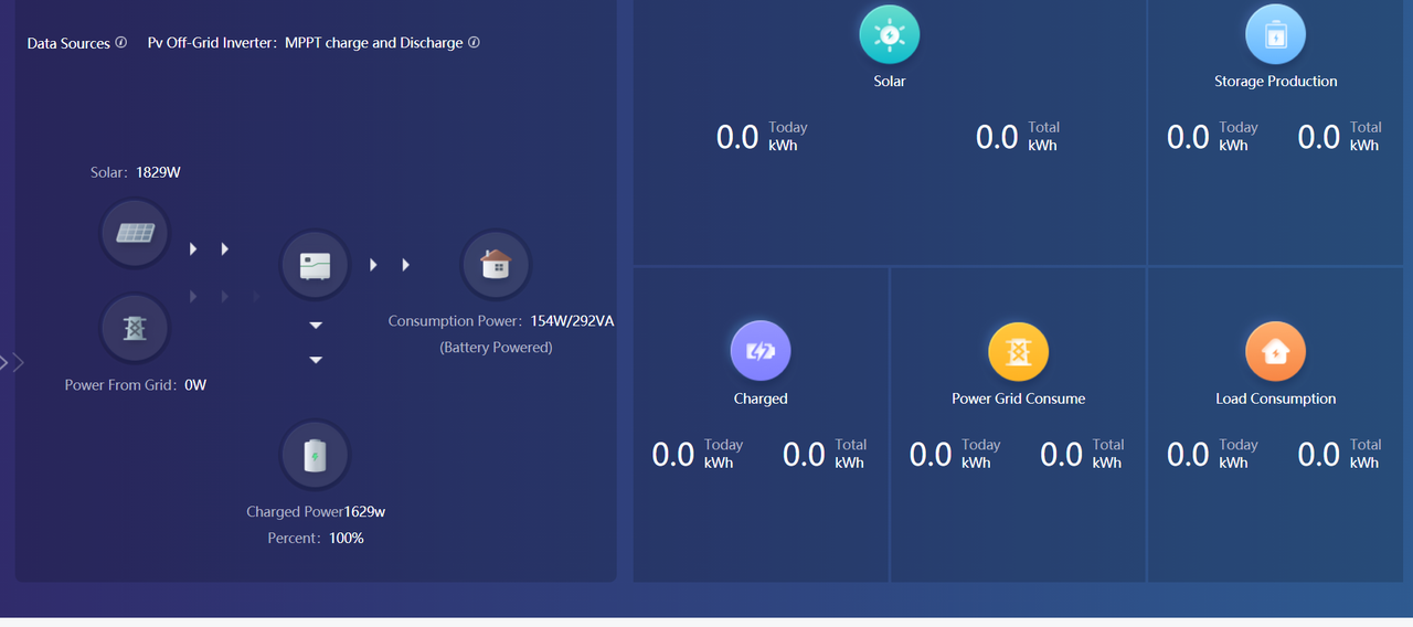
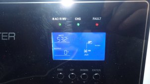
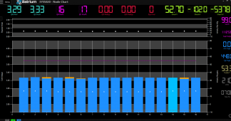
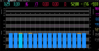
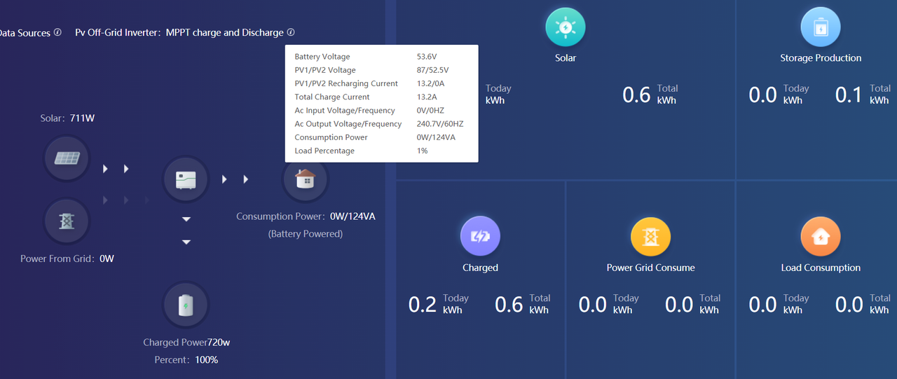
While I waiting for growatt to call back I decided to test the charge function on the inveter which is working perfectly. Set it for max 40 amps on the server and saw a max of 16.89 going to the battery. Inverter fans did turn on but were not very loud.


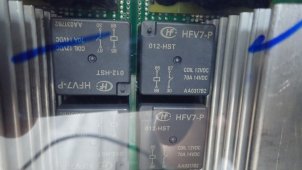
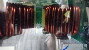
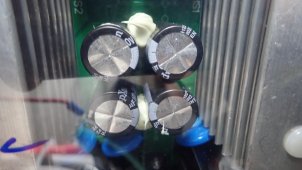
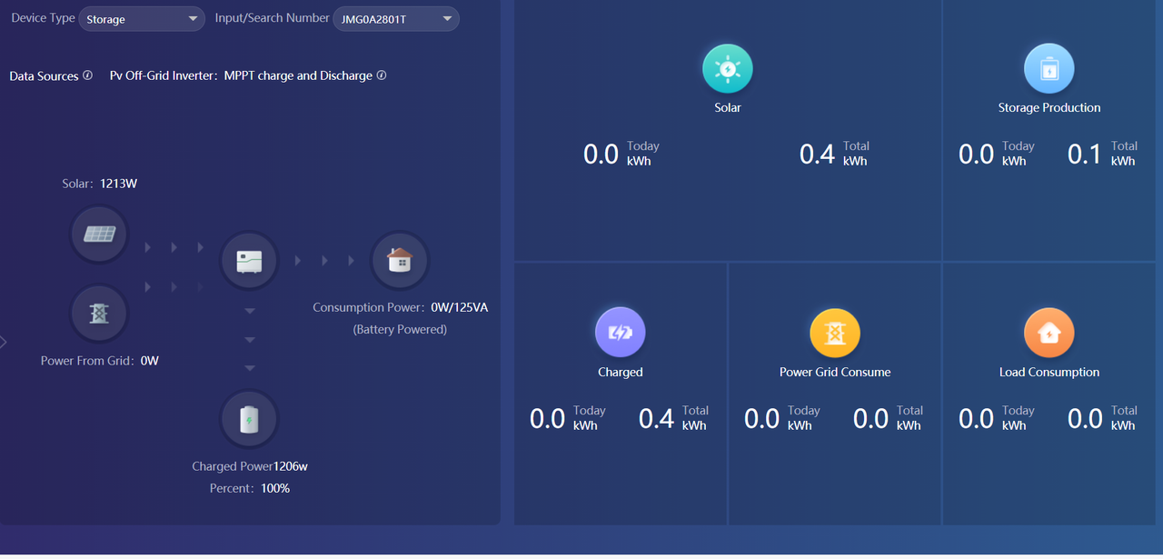
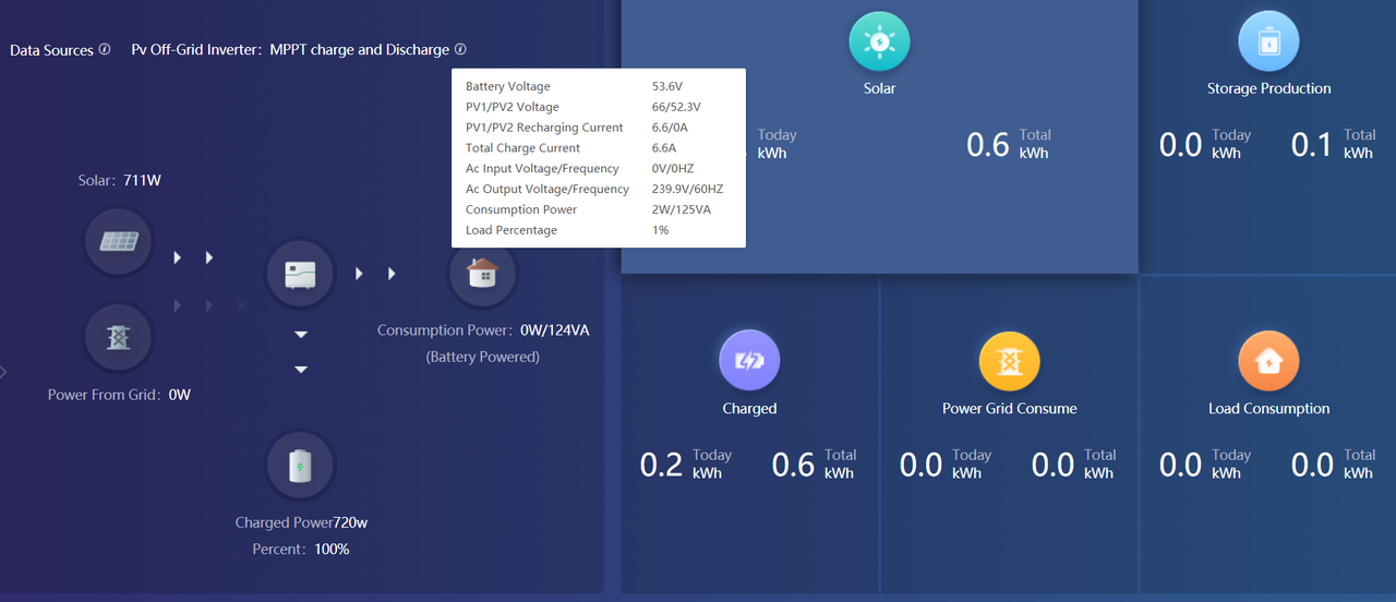
Update Additional Details:


Update:

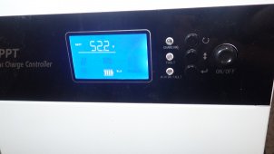
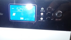
Very happy to see all the batteries are at the same voltage. I was very curious to see how they would do on charge up and they balanced together very quickly.
 
Last edited:
I talked to signature solar today, was told neutral is required, I was told if charging from the grid or generator the neutral should not be connected.

Udpated:
Second call went better but my first test created an odd issue they have not seen and will require further testing.

If connected to grid, the neutral should already be connected to ground in main breaker panel for grid.
If not connected to grid, neutral should be connected to ground at the inverter, and should have a ground rod.

Not sure if anyone has heard of this, I'm getting proper output 113v, 110v measured on main legs of the breaker. Soon as one breaker is turned on that goes to the outlets in the tv that has a fan attached one leg goes to zero and the other goes to 240v.

Do you have neutral connected from inverter to the panel with these breakers?
 
If connected to grid, the neutral should already be connected to ground in main breaker panel for grid.
If not connected to grid, neutral should be connected to ground at the inverter, and should have a ground rod.


Do you have neutral connected from inverter to the panel with these breakers?
Hello Hedges, It is connected, I verified everything with signature before powering up.
I'm going to move the battery to the second inverter and test today with it and see if the problem repoduces it self.
 
Update: Moved the battery over and setup the second inverter: Only delta is the first one I updated the firmware.

Key differences observed:
First Inverter: h1/h2 113v - 110v

Second Inverter: h1/h2 both sitting at 120v

It was very happy to see one side of the house up and running, now I will email the results to signature and update the response.
 
Updated, Adjusted the charger settings to match my voltmeter settings as the inverter was charging slightly higher than observed at the battery. Charging had finished before the AC unit turned on and it went to fault error code 51.
Before the ac turned, I was watching the amps here are the observed amperages:
Battery was reading 7.89 amps, measured output on the inverter was 1.86.

Going to retest on grid and double check amp pulls.
 
Here's the update voltages when the AC is on,

L1 - base amps 1.94, AC on 19.67
L2 - base amps .88, AC on 17.77
If the math is right that should be 8,985.6, but with a 36kwh surge I thought it would handle that. As I was told it handles 4ton ac including additional loads.

So what could be the issue? Settings, wire gauge but its all 2/0 around 6ft in length?
 
Talked with John at signature and went very well today. John recommend doubling the cabling and testing again, also wanted me to swap my spare boards that into the that is not function properly. But unfortantely the holes that were tapped into the heatsink were very far off so could not proceed till they new ones come in on friday.
 
When I ordered the cable back in october of 2020 the manufacture stated it was 325amps which is way over its rated, I should have double checked that. Going to make a few taps and double the cable and retest.
 

Attachments

  • nec-ampacities.pdf
    673.8 KB · Views: 4
Growatt called me today from my support email, they were very nice and helpful. Unfortantely the back spare board I had the standoffs were tapped completely out of alighment so waiting on a new on to proceed with testing. John at signature requested to change out both boards and they will be here friday.
 
Boards came into day and I have swapped them in. Tomorrow morning, I will go back over all the connections and then test the inverter.
Here's bunch of shots of all the wiring, they are all nicely numbered.
 

Attachments

  • P6100845.JPG
    P6100845.JPG
    103.4 KB · Views: 19
  • P6100846.JPG
    P6100846.JPG
    260 KB · Views: 19
  • P6100847.JPG
    P6100847.JPG
    266.7 KB · Views: 16
  • P6100848.JPG
    P6100848.JPG
    251.9 KB · Views: 16
  • P6100849.JPG
    P6100849.JPG
    246.1 KB · Views: 17
  • P6100850.JPG
    P6100850.JPG
    248.9 KB · Views: 16
  • P6100851.JPG
    P6100851.JPG
    296.9 KB · Views: 16
  • P6100854.JPG
    P6100854.JPG
    279.2 KB · Views: 18
  • P6100855.JPG
    P6100855.JPG
    258.2 KB · Views: 15
  • P6100860.JPG
    P6100860.JPG
    263.6 KB · Views: 18
Few more.
 

Attachments

  • P6100861.JPG
    P6100861.JPG
    112.6 KB · Views: 6
  • P6100863.JPG
    P6100863.JPG
    378.3 KB · Views: 6
  • P6100864.JPG
    P6100864.JPG
    209.8 KB · Views: 6
Completed the board swap late last night and wanted a fresh start today since there were a lot of cables to hookup. The Inverter output was very simliar to the second both legs were 118.8. Did load test of all the friges, freezers, window ac and passed. John at signaturesolar was very helpful in suggestions to try and resolve the issue
 
Completed the wire doubling for both inverters, need to work ongetting the organized a little better tomorrow.
 

Attachments

  • P6110878.JPG
    P6110878.JPG
    205.7 KB · Views: 22
  • P6110877.JPG
    P6110877.JPG
    229.7 KB · Views: 20
  • P6110876.JPG
    P6110876.JPG
    234.5 KB · Views: 21
  • P6110873.JPG
    P6110873.JPG
    238.7 KB · Views: 22
  • P6110872.JPG
    P6110872.JPG
    294.9 KB · Views: 20
  • P6110871.JPG
    P6110871.JPG
    309.3 KB · Views: 19
  • P6110870.JPG
    P6110870.JPG
    261.9 KB · Views: 22
  • P6110869.JPG
    P6110869.JPG
    278.9 KB · Views: 23
You might be able to flip one ring terminal face up, one face down so they don't have to be at different angles.
I was curious to get feedback, John wanted me to double the connections and test again.
I played around before crimping but this seem to be the best way to keep them flat against each other and the back terminal. The shunt had room to flip so it looks nicer but I did wonder how other people did this. John had stated that many double the 2/0 cable. Also took the time to shrink them all but ran out near the last few. I will try flipping on the smaller breaker as it was missing the backing plate. I did not even think of trying it on that one but bet it has room.
 
Last edited:
Decided to really further balance the two breaker boxes, moved the dryer off the one that has the heating cooling and 5 other connections. My lowes is really missing a lot they said wires was very hard to get. They were stocked full of junction boxes but had zero covers. I like how the loads look now and it’s much more balanced. They originally had all 240 on one and 110v on another, my previous home was more distributed. I need to work tomorrow on cleaning up the wires and getting them zip tied.
 

Attachments

  • P6120883.JPG
    P6120883.JPG
    318.9 KB · Views: 15
  • P6120882.JPG
    P6120882.JPG
    315.8 KB · Views: 15
  • P6120881.JPG
    P6120881.JPG
    219.9 KB · Views: 15
Slowing bring everything back on for inveter 1, turned on the charge controller and configured. There is a voltage difference between it and the inverter. I have adjusted the settings down in the charger to account for the difference. I found the growatt inverter would charge .4 higher that what I had set it for in the server. I will have to carefully watch the growatt charge controller and see how it charges.
 

Attachments

  • P6130889.JPG
    P6130889.JPG
    151.2 KB · Views: 7
  • P6130888.JPG
    P6130888.JPG
    222.6 KB · Views: 7
Short test of the charge controller after configuration with 8 pannels online it produced 45.56 amps.
 

Attachments

  • P6130892.JPG
    P6130892.JPG
    181.1 KB · Views: 3
Pulled anywhere between 5400-5800 watts, doubling the cable fixed the issues. Based on discharge rate I wonder about night time, when I brought the full array online for the charge controller it easily charged under this load. I'm thinking I will break up the heating/cooling breakers. Maybe the growatt server is down, no data loggers are working today.
 

Attachments

  • ac test.png
    ac test.png
    137.1 KB · Views: 5
  • hearter test growatt.png
    hearter test growatt.png
    135.7 KB · Views: 6
Back
Top