


You are using an out of date browser. It may not display this or other websites correctly.
You should upgrade or use an alternative browser.
You should upgrade or use an alternative browser.
Very new to solar but started purchasing items, not sure of the final specs of the whole system.
- Thread starter kromc5
- Start date
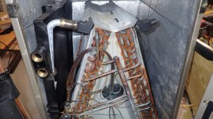
It's inverter 1 I have not removed the cover on it yet going as I will wait for signature to call. The smell was completely overwhelming from the fans.Search with your nose. Cooked electronics maintains its odor long after flames are no longer visible.
Could be your system (most likely), might be something else.
Got to speak with Richard from signature very nice and helpful. He originally spoke of returning the whole unit but hopefully we can just replace the boards. We went back through the configuration panels etc and he did not see an issue. When they send the RMA I told them I would provide all the logs for voltages, current etc.
Update: Was told I'm over paneled but new recommendation is now to under panel, I'm still waiting on clarification. I have looking at other controllers and inputs, this is very cool config from midnite. I may have to dig up 125 of wire or buy new controllers not sure yet.
MidNite Solar - Classic Sizing Tool.
MidNite Solar is the industry leader and manufacture of quality Renewable Energy System electrical components and E-Panels.
www.midnitesolar.com
MrM1
I'm Here, But I'm Not All There
MidNite is the best. And their sizing tool is the bomb. For me it's hard to use any thing else. Their classic series SCC is Way crazy customizable and can be way overpaneled.
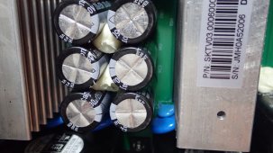
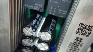
Had to get more 3 inch pipe to tie in to the house and run another 75 ft of 6awg. I have split all the connections on the larger row of the panels. The interesting question is will this produce more power? One inverter, one charge controller now have 9 panels on each pv input. Inverter 2 has 9 on one pv and 6 on the second. Also interesting the replacement board for my 150v inverter has 6 250v caps instead of 4 160v caps.
Attachments
-
 PA280001.JPG674.4 KB · Views: 14
 -
 PA280010.JPG213.5 KB · Views: 14
 -
 PA280009.JPG242.9 KB · Views: 13
 -
 PA280008.JPG290.9 KB · Views: 13
 -
 PA280007.JPG368.4 KB · Views: 13
 -
 PA280006.JPG383.2 KB · Views: 12
 -
 PA280005.JPG394.9 KB · Views: 13
 -
 PA280004.JPG422.5 KB · Views: 13
 -
 PA280003.JPG274.2 KB · Views: 13
 -
 PA280002.JPG186.5 KB · Views: 13
Had to get more 3 inch pipe to tie in to the house and run another 75 ft of 6awg. I have split all the connections on the larger row of the panels. The interesting question is will this produce more power? One inverter, one charge controller now have 9 panels on each pv input. Inverter 2 has 9 on one pv and 6 on the second. Also interesting the replacement board for my 150v inverter has 6 250v caps instead of 4 160v caps, I doubled check via two sources before installing to be safe.
Attachments
MrM1
I'm Here, But I'm Not All There
Did you get the new boards installed? Do you think they will be more robust?
So you had to break up the arrays? It would be interesting to see see a comparison between your old arrays designs (series / parallel / number of PV inputs / number of SCCs) to your current or planned new set up.
- what are the differences in VOC per pv input
- differences in array watts per pv input
I did go on and install the new board, waiting on one from signature but wanted to get back up and testing quickly.Did you get the new boards installed? Do you think they will be more robust?
So you had to break up the arrays? It would be interesting to see see a comparison between your old arrays designs (series / parallel / number of PV inputs / number of SCCs) to your current or planned new set up.
- what are the differences in VOC per pv input
- differences in array watts per pv input
PV voltage is all the same, Original max if pc per input would have been 6650 on the lower side of the total output.
Now the pv inputs for inverter 1 and charge controller one each have 3330w, Inverter two has one at 3330w and 2220. I believe I could pull the 125ft of wire from the conduit using the winch but I wonder if I could get it back through with the extra 6/2 wire added? I want to split the other arrays as well but unsure if I can succeed.
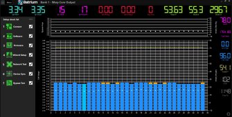
Let me add with 18 on one pv input the max amps I recorded was 54. I brought everything online with no loads this evening will switch back over tomorrow but unsure since two SCC are offline. I may just unplug a few arrays to at least have 3 SCC online. Still working on the 4th one.
Last edited:
MrM1
I'm Here, But I'm Not All There
Nice. Thx for the update
MrM1
I'm Here, But I'm Not All There
In the big picture looking back, do you think your SCC got smoked from being over paneled? Or some other reason?
Hedges
I See Electromagnetic Fields!
- Joined
- Mar 28, 2020
- Messages
- 20,635
Had to get more 3 inch pipe to tie in to the house and run another 75 ft of 6awg. I have split all the connections on the larger row of the panels. The interesting question is will this produce more power? One inverter, one charge controller now have 9 panels on each pv input. Inverter 2 has 9 on one pv and 6 on the second. Also interesting the replacement board for my 150v inverter has 6 250v caps instead of 4 160v caps, I doubled check via two sources before installing to be safe.
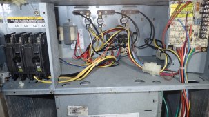
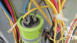
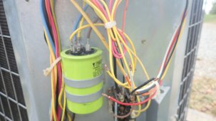
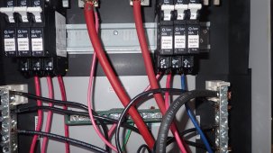
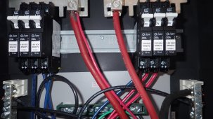
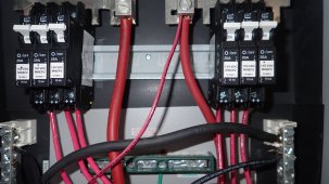
Your pictures have a couple skinny wires going to same lug as fat wire, fed by 3x 20A circuits.
What is that for? It isn't protected for the current it would carry if shorted. You have spare tabs on the combiner bar, so could install a breaker for it.
The small wire is for the midnite surge suppressors.Your pictures have a couple skinny wires going to same lug as fat wire, fed by 3x 20A circuits.
What is that for? It isn't protected for the current it would carry if shorted. You have spare tabs on the combiner bar, so could install a breaker for it.
I was specifically told I was over-paneled, I was told by one tech to keep it under 6 panels another 12. I have broken themIn the big picture looking back, do you think your SCC got smoked from being over paneled? Or some other reason?
up to 9 panels per pv input. I left everything online even though inverter 1 has a minor issue and it no longer reads the pv input properly. There are no errors and its does generate pv, tomorrow will be an interesting day for data. Get to see if the current generated is simliar to what was seen prior. I still do not have a firm answer on the charge controllers though.
Hedges
I See Electromagnetic Fields!
- Joined
- Mar 28, 2020
- Messages
- 20,635
The small wire is for the midnite surge suppressors.
Slow-blow fuse or time-delay breaker would be appropriate.
The wires appear to route near opposite polarity busbars, and probably can't carry short-circuit current from array.
Or at least an extra protective sleeve. For routing of twisted pair cable inside my inverters, the accessory kits came with a silicone tube intended to contain splatter if wire blew (like fusible link in car.)
I think the Midnight suppressors have MOVs with thermistor or similar device to open the circuit if MOV fails shorted. Some status lights, would show protected/blown in an AC application but I think their instructions said some of that doesn't light up for DC.
e.g. using parts like these:
TMOV20RP460M Littelfuse Inc. | Circuit Protection | DigiKey
Order today, ships today. TMOV20RP460M – 750 V 10 kA Varistor 1 Circuit Through Hole Disc 20mm 3-Lead from Littelfuse Inc.. Pricing and Availability on millions of electronic components from Digi-Key Electronics.
Thank you for the information I will look addressing the wires. Sadly having to pull all the wires once and then move everything around has left the wiring not very clean from the panels/combiners. I have alot of wiring cleanup that needs to be done.Slow-blow fuse or time-delay breaker would be appropriate.
The wires appear to route near opposite polarity busbars, and probably can't carry short-circuit current from array.
Or at least an extra protective sleeve. For routing of twisted pair cable inside my inverters, the accessory kits came with a silicone tube intended to contain splatter if wire blew (like fusible link in car.)
I think the Midnight suppressors have MOVs with thermistor or similar device to open the circuit if MOV fails shorted. Some status lights, would show protected/blown in an AC application but I think their instructions said some of that doesn't light up for DC.
e.g. using parts like these:
TMOV20RP460M Littelfuse Inc. | Circuit Protection | DigiKey
Order today, ships today. TMOV20RP460M – 750 V 10 kA Varistor 1 Circuit Through Hole Disc 20mm 3-Lead from Littelfuse Inc.. Pricing and Availability on millions of electronic components from Digi-Key Electronics.www.digikey.com
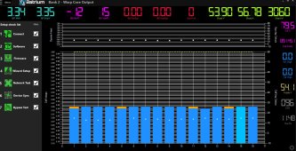
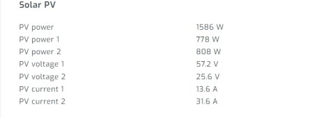
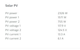
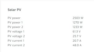
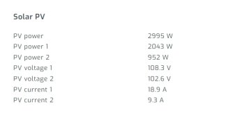
Sunny with slight haze charge rates are way down, one problem found both pv inputs have the exact same panels. I will swap the pv inputs and see if the low output. Aslo seeing simliar low rates on inveter 2 and large delta in pv current. 4th pic.
Attachments
Last edited:
MrM1
I'm Here, But I'm Not All There
So you got right about 3000 watts coming in to each PV input so far this morning from each array?
If you take the lowest watt number the panels can produce its 3330. Its fustrating to see both inveters with large deltas in pv current since they both have identical panels/numbers on each pv input.So you got right about 3000 watts coming in to each PV input so far this morning from each array?
Still have a large delta in pv current but it jumped up and is now producing more than before: If both sides were doing 40+ amps I would be very happy. I have verified the pv voltage twice this morning but since it's reading both inputs wrong, I wonder if that is causing the disparity.
Attachments
Hedges
I See Electromagnetic Fields!
- Joined
- Mar 28, 2020
- Messages
- 20,635
Same power from PV1 and PV2, but 2x difference in voltage and current?
Sure you don't have something like 2x string length on on array compared to other ?? ?
Or maybe shading causing similar effect?
(one of three images you posted showed similar voltage, half current and power for one. That could be shading or open string. Got a clamp DC ammeter to check strings?)
Sure you don't have something like 2x string length on on array compared to other ?? ?
Or maybe shading causing similar effect?
(one of three images you posted showed similar voltage, half current and power for one. That could be shading or open string. Got a clamp DC ammeter to check strings?)
Similar threads
- Replies
- 52
- Views
- 4K