


AlaskanNoob
Solar Enthusiast
- Joined
- Feb 20, 2021
- Messages
- 902
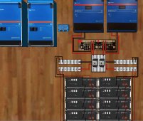
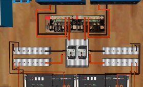
I'm planning for 2 x 450/200 SmartSolar MPPTs in parallel to supply a combined 400 amp for charging a 48V battery bank.
Assuming perfect sunny day and MPPTs are producing full 400 amp for charging.
The current will go from the MPPTs through 1 AWG wires (can carry 200 amp) to a set of Lynx DC Distributors. All four circuits going through the Lynx will have 250 amp Mega Fuses (not shown).
The DC charging current leaving the Lynx goes in two separate but otherwise identical paths, using 1 AWG wires. Each path goes through a C/B and then to a bus bar. From the bus bar the current is split into two paths using 4AWG wire that is rated for 100 amp. Then into four 48V batteries wired in parallel. Battery Bank A and Battery Bank B for a total of 8 batteries wired in parallel (through the Lynx).
Question is. What happens if a lightning strike or something causes isolation of Battery Bank A or Battery Bank B? (Battery Bank A being 4 batteries on the left, B the four on the right). A fuse and/or C/B pops, and 4 of the 8 batteries are isolated from the system. Will the two MPPTs continue to produce 400 amp to send to the batteries? Will the Victron System know half the batteries are offline because of something abnormal since the Pylontech batteries communicate with the Multiplus inverters or Cerbo GX (comm wires not shown). Can I program the Victron system to throttle charge to 200A max if all batteries are not online?
If the MPPTs don't throttle the charging power in response to this event, I would assume this would lead the other battery path fuse and/or C/B to pop and thereby all batteries would be isolated. What happens to the current then? Do the MPPTs still produce it and where does it go? I assume the MPPTs stop pushing the current because there is no longer a demand for it (from the batteries) so it will just travel to the inverters if needed.
Note, I cannot increase the size of the cables from the batteries to the buses for this scenario because Pylontech uses a proprietary terminal connector that is limited to about 130 amp.
Thanks for any education you can offer!
Attachments
Last edited:

