diy solar

diy solar

Victron Multiplus cool functionality

sneil

New Member
Joined
Jul 18, 2022
Messages
37
Location
Outside Denver, CO
I had a MultiPlus 12/3000/120-50 120V installed in our 5th wheel along with a Victron MPPT 150/85 and 300Ah (3 x 100Ah) Battleborn batteries. Everything worked great with that Multiplus, but I had an opportunity to upgrade to the new MultiPlus-II 12/3000/120-50 2x120V.

I was going over the the MP II settings during the install and ran across a new (to me) feature called AC input control. After reading the details of what you can do with it I decided to give a try. MP II AC Input Control allows me to selectively decide when to ignore the AC coming in from shore power if I have enough battery capacity, adequate solar and even inverter load. I've been testing this out over the past couple of days and it's working quite well.

I set the MP II to use the following Load & Battery conditions:
  • ignore AC input if the load is 1000W or less for 30 seconds
  • accept AC input if the load goes above 1500W for 1 minute
  • accept AC input if SOC drops below 50%
  • ignore AC input after absorption finished
I've only had this setup a couple of days and so far it seems to work perfectly. I'm now seeing PV and battery being preferred until the SOC drops below 50% then the AC is accepted and charges the battery bank back up and then ignores the AC input again. This has reduced the amount of time I'm using shore power which is what I was looking to do and do it automatically. With electric costs increasing I think this will help in reducing those costs.

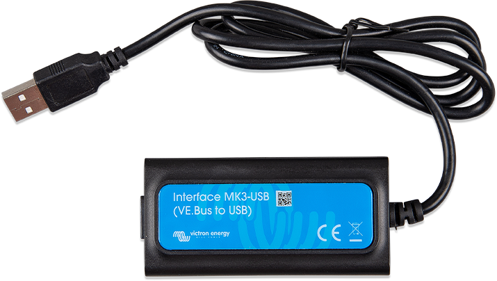
I hadn't seen anything about this feature and thought others might find it useful. As a bonus, I was able to set this up using the Victron Connect app (and MK3 dongle) instead of having to use VE Configure.
 
That's awesome.

FWIW, all Victron VE.Bus (MP, Quattro) have this capability. The versions prior to "II" required the use of "assistants" that allowed one to set various voltage, power and SoC based criteria for when to ignore/accept AC.

Pretty snazzy that they've made it a separate feature set in VC. That's the one thing VC doesn't support right now is assistants, and assistants can provide crazy functionality.
 
I had a MultiPlus 12/3000/120-50 120V installed in our 5th wheel along with a Victron MPPT 150/85 and 300Ah (3 x 100Ah) Battleborn batteries. Everything worked great with that Multiplus, but I had an opportunity to upgrade to the new MultiPlus-II 12/3000/120-50 2x120V.

I was going over the the MP II settings during the install and ran across a new (to me) feature called AC input control. After reading the details of what you can do with it I decided to give a try. MP II AC Input Control allows me to selectively decide when to ignore the AC coming in from shore power if I have enough battery capacity, adequate solar and even inverter load. I've been testing this out over the past couple of days and it's working quite well.

I set the MP II to use the following Load & Battery conditions:
  • ignore AC input if the load is 1000W or less for 30 seconds
  • accept AC input if the load goes above 1500W for 1 minute
  • accept AC input if SOC drops below 50%
  • ignore AC input after absorption finished
I've only had this setup a couple of days and so far it seems to work perfectly. I'm now seeing PV and battery being preferred until the SOC drops below 50% then the AC is accepted and charges the battery bank back up and then ignores the AC input again. This has reduced the amount of time I'm using shore power which is what I was looking to do and do it automatically. With electric costs increasing I think this will help in reducing those costs.

I hadn't seen anything about this feature and thought others might find it useful. As a bonus, I was able to set this up using the Victron Connect app (and MK3 dongle) instead of having to use VE Configure.
Wow! I am learning the difference in Multiplus inverter and perhaps will upgrade to a Multiplus II. But I am having a problem! it just happens that I finish building my Van tree weeks ago an living in it full time. My electrical setup is working at 85%. Meaning, that all my small appliances I plugged in to any receptacle works perfectly! Fridge, TV, Laptop, etc.

But when I went to turn on my water heater, the fuse connected to the 4/0 cable going to the inverter, turned red hot and did not blow! The fuse is a 350Amp and the center of the fuse is made with a black hard plastic. This part seams to be melting in the heating process. Can you try to troubleshoot my problem? I really need the help.

Don’t know everything about the electrical, but I learn through out the way…Just looking for a little help from an experience owner. Thank you. My name is Jose. Hope you may help me on this frustrating issue. Hope to talk soon.
 
@JMR53

It is usually best to start your own thread to solve a problem.

But I will try to help…

To start, we need to know all the details on your system.
System:
What inverter are you using?
What size of wires between batteries and inverter?
What type of fuse is heating up?
What battery capacity do you have?

Load
How many watts is the big load (water heater) using?
How much other load is on your system?

Other, do you have any other pieces of equipment installed that can help troubleshoot? Smartshunt? Cerbo? Clamp on Multimeter that reads amps?

My guess is you may be overloading your system with the water heater. But we need to figure it out first.
 
That's awesome.

FWIW, all Victron VE.Bus (MP, Quattro) have this capability. The versions prior to "II" required the use of "assistants" that allowed one to set various voltage, power and SoC based criteria for when to ignore/accept AC.

Pretty snazzy that they've made it a separate feature set in VC. That's the one thing VC doesn't support right now is assistants, and assistants can provide crazy functionality.
Do you know if any of that is configurable without a Windows PC at all? Through the Cerbo GX?
 
The Cerbo has very limited options on changing settings. Right now, if you want to do full feature configuration, you need VEConfig on Windows.
How does a PC/Laptop with VEConfig communucate with a Multiplus II? Is there a specific cable required?
 
I had a MultiPlus 12/3000/120-50 120V installed in our 5th wheel along with a Victron MPPT 150/85 and 300Ah (3 x 100Ah) Battleborn batteries. Everything worked great with that Multiplus, but I had an opportunity to upgrade to the new MultiPlus-II 12/3000/120-50 2x120V.
Does that mean you actually own one?
I was going over the the MP II settings during the install and ran across a new (to me) feature called AC input control. After reading the details of what you can do with it I decided to give a try. MP II AC Input Control allows me to selectively decide when to ignore the AC coming in from shore power if I have enough battery capacity, adequate solar and even inverter load. I've been testing this out over the past couple of days and it's working quite well.

I set the MP II to use the following Load & Battery conditions:
  • ignore AC input if the load is 1000W or less for 30 seconds
  • accept AC input if the load goes above 1500W for 1 minute
  • accept AC input if SOC drops below 50%
  • ignore AC input after absorption finished
I've only had this setup a couple of days and so far it seems to work perfectly. I'm now seeing PV and battery being preferred until the SOC drops below 50% then the AC is accepted and charges the battery bank back up and then ignores the AC input again. This has reduced the amount of time I'm using shore power which is what I was looking to do and do it automatically. With electric costs increasing I think this will help in reducing those costs.

I hadn't seen anything about this feature and thought others might find it useful. As a bonus, I was able to set this up using the Victron Connect app (and MK3 dongle) instead of having to use VE Configure.
Sounds like you do (12V).

Are you using it to power 120VAC loads only or also 240VAC loads (when grid-tied)?
 
1) MK3-USB adapter and either VictronConnect or VEConfig.
2) Download config file from VRM, edit/save it in VEConfig, and upload it via VRM.
Got it - so just a USB adapter cable between the Multiplus II and a laptop to enable communication.

Sounds pretty straightforward.

Victron sells an optional external CT sensor and I’m interested to find any owners who are using the 120x2 Multiplus II to offset grid-side load using this external CT sensor.

I assume this should only allow grid-side loads of L1 to be offset while L2 loads continue to be grid-powered, but I’d really like to find an owner of the 12V or 24V model to confirm this…
 
Got it - so just a USB adapter cable between the Multiplus II and a laptop to enable communication.


Not needed if you already have a Cerbo and VRM.

Sounds pretty straightforward.

Victron sells an optional external CT sensor and I’m interested to find any owners who are using the 120x2 Multiplus II to offset grid-side load using this external CT sensor.

I assume this should only allow grid-side loads of L1 to be offset while L2 loads continue to be grid-powered, but I’d really like to find an owner of the 12V or 24V model to confirm this…

The only time the MP-II x2 can provide loads on L2 is when L1 and L2 are shorted on the input, so the MP-II x2 shorts L1 and L2 on the output providing 120V to both legs, but 0V between L1 and L2.
 

Not needed if you already have a Cerbo and VRM.
$73 for a USB cable? Ouch! I’m guessing a Cerbo and VRM are even pricier?
The only time the MP-II x2 can provide loads on L2 is when L1 and L2 are shorted on the input, so the MP-II x2 shorts L1 and L2 on the output providing 120V to both legs, but 0V between L1 and L2.
Yes, that’s what I understood. But it offers an external CT sensor so I’m assuming that by clamping that CT sensor around the L1 mains wire, you can configure the Multiplus II 2x120V to at least offset loads on L1…

I’m not as interested in backup capability as I am to used battery energy stored during daylight hours to offset overnight loads (time shift).

I just want to drain the battery offsetting loads (and reducing consumption from grid) as the night wears on, so for that purpose, twice as long offsetting loads on one leg only is as effective as offsetting loads on both legs for half as long…

I just need to confirm that he use of the optional CT sensor can allow the Multiplus II 2x120x to function in the manner I am hoping…
 
$73 for a USB cable? Ouch! I’m guessing a Cerbo and VRM are even pricier?

It's not a cable. It's an adapter. I allows communication between USB and the VE.Bus interface.

Yes. Cerbo is much more expensive.

No. VRM is "free" with your purchase of a GX device. :p

Yes, that’s what I understood. But it offers an external CT sensor so I’m assuming that by clamping that CT sensor around the L1 mains wire, you can configure the Multiplus II 2x120V to at least offset loads on L1…

I really don't know. With Assistants, crazy things are possible. Default MP behavior is to pass through AC-in to loads and charge battery with surplus. Even without a CT sensor (know nothing about them), you could instruct the MP to "Ignore AC-in" based on some criteria like voltage, SoC, and inverter load. If votlage or SoC are too low, or inverter load is too high, you can fall back to AC-in. That AC-in can also be limited to never more than X Amps, and the inverter can supplement that amount with PowerAssist.

I’m not as interested in backup capability as I am to used battery energy stored during daylight hours to offset overnight loads (time shift).

I just want to drain the battery offsetting loads (and reducing consumption from grid) as the night wears on, so for that purpose, twice as long offsetting loads on one leg only is as effective as offsetting loads on both legs for half as long…

I just need to confirm that he use of the optional CT sensor can allow the Multiplus II 2x120x to function in the manner I am hoping…

I'm not entirely convinced you need CT sensor. What logic do you wish to apply to CT sensor data?
 
It's not a cable. It's an adapter. I allows communication between USB and the VE.Bus interface.

Yes. Cerbo is much more expensive.

No. VRM is "free" with your purchase of a GX device. :p
I guess you’ve got to pay to play…
I really don't know. With Assistants, crazy things are possible. Default MP behavior is to pass through AC-in to loads and charge battery with surplus.
Are ‘Assistants’ various presets you can configure?

In my case, I’m looking primarily at overnight behavior, so no solar power and I am trying to prevent any export from grid.
Even without a CT sensor (know nothing about them), you could instruct the MP to "Ignore AC-in" based on some criteria like voltage, SoC, and inverter load.
A CT sensor clamps around the main wire incoming from the grid (L1 wire in the case of the MP2x120) and communicates the level of grid consumption of export to grid through that wire.

I don’t want the MP2x120 to ignore ‘AC-in’, I want it to invert battery energy and push it out the the L1 AC input until the CT sensor communicates to import and no export on L1 (zero net consumption on L1).

Having the MP2x120 supply all L1 liads on AC output is easy, but I also want it to supply all L1 loads on AC input (main panel loads directly tied to grid).
If votlage or SoC are too low, or inverter load is too high, you can fall back to AC-in. That AC-in can also be limited to never more than X Amps, and the inverter can supplement that amount with PowerAssist.
Understand all of that, but those features are all for downstream loads connected to AC output. The CT sensor allows much of that capability to also applied upstream to loads on AC input (I hope)…
I'm not entirely convinced you need CT sensor. What logic do you wish to apply to CT sensor data?
Again, I want all of the capability that a Multiplus 2x120 offers to loads on AC output to be extended upstream to loads on AC input. The external CT sensor allows the MP2x120 to measure / monitor load consumption on the AC input side as effectively as the interval CT sensors allow it to measure / monitor load consumption on AC output.
 
I guess you’ve got to pay to play…

Truth.

Are ‘Assistants’ various presets you can configure?

Pretty much.

In my case, I’m looking primarily at overnight behavior, so no solar power and I am trying to prevent any export from grid.

Export from grid. In this context, wouldn't one say export to grid?

Are you configured for grid interaction (grid-tie)?

A CT sensor clamps around the main wire incoming from the grid (L1 wire in the case of the MP2x120) and communicates the level of grid consumption of export to grid through that wire.

Okay.

I don’t want the MP2x120 to ignore ‘AC-in’, I want it to invert battery energy and push it out the the L1 AC input until the CT sensor communicates to import and no export on L1 (zero net consumption on L1).

Again, default behavior is to passthru AC-in to battery charger/loads. In order to invert from battery, you will have to activate "Ignore AC-in"

Having the MP2x120 supply all L1 liads on AC output is easy, but I also want it to supply all L1 loads on AC input (main panel loads directly tied to grid).

Ah. This is what I was missing. You're in a realm where I'm clueless.

Understand all of that, but those features are all for downstream loads connected to AC output. The CT sensor allows much of that capability to also applied upstream to loads on AC input (I hope)…

No idea.

Again, I want all of the capability that a Multiplus 2x120 offers to loads on AC output to be extended upstream to loads on AC input. The external CT sensor allows the MP2x120 to measure / monitor load consumption on the AC input side as effectively as the interval CT sensors allow it to measure / monitor load consumption on AC output.

Gotcha. I'll be watching your progress with interest.
 
Does that mean you actually own one?

Sounds like you do (12V).

Are you using it to power 120VAC loads only or also 240VAC loads (when grid-tied)?
I had the previous version of the Multiplus in the RV but it was limited to only L1. I switched to the Multiplus II (2x120) which supports L1 & L2 and can provide inverter power to both sides of the RV circuit panel.

The RV only uses 120VAC, no 240VAC items. So far (3 months since switching) the Multiplus II has performed exactly as I expected and has been a worthwhile upgrade from the original. I also really like the AC input control capability that allows me to utilize the battery bank even while connected to shore power and only allowing shore power in if the loads increase to my set limit or the battery bank gets to the low limit I set.

I'd like to increase the battery bank and solar panels to collect and store more energy in the near future.
 
Export from grid. In this context, wouldn't one say export to grid?
Typo (since fixed) - I meant import from grid.
Are you configured for grid interaction (grid-tie)?
Yes, 99.9% of use is tied to grid (using for my house).
Again, default behavior is to passthru AC-in to battery charger/loads. In order to invert from battery, you will have to activate "Ignore AC-in"
Yes, “ignore AC in” uses the internal CT sensor on the AC input to throttle the inverter to producing just enough power to offset consumption on the AC output (so no power being imported through the AC input).

The external CT sensor should allow the capability of pushing the ‘boundary’ of “AC in’ out to the incoming grid connection, so the inverter can be controlled to generate sufficient power to offset both loads on AC output as well as loads on AC input (non critical loads).
Ah. This is what I was missing. You're in a realm where I'm clueless.
I'll be watching your progress with interest.
Reached out to Victron for confirmation of this capability and will let you know :).
 
I had the previous version of the Multiplus in the RV but it was limited to only L1. I switched to the Multiplus II (2x120) which supports L1 & L2 and can provide inverter power to both sides of the RV circuit panel.
Meaning you had a 120VAC Multiplus connected to one leg of the 240VAC shore power in your RV and is was able to use the external CT sensor to offset loads on both AC input as well as AC output?

That’s what I would have expected and so I just want to confirm that that capability remains in place for the Multiplus II 120x2 (for L1, understand no loads on L2 can be offset when grid-tied).

Was it easy to switch from the default mode of ‘ignore AC in’ using the internal CF sensor to the equivalent using te external CT sensor?


The RV only uses 120VAC, no 240VAC items. So far (3 months since switching) the Multiplus II has performed exactly as I expected and has been a worthwhile upgrade from the original.
So your RV when grid-tied is essentially 2 out of phase 120VAC sources each feeding half of your loads and while the new Multiplus II 120x2 allows you to continue to power both half-panels worth of load off of battery power when disconnected fro grid, correct?
I also really like the AC input control capability that allows me to utilize the battery bank even while connected to shore power and only allowing shore power in if the loads increase to my set limit or the battery bank gets to the low limit I set.
And are you using the external CT sensor for that control? (Offsetting loads on AC input as well as AC output using battery power?)

Whether using the external CT sensor or the internal CT sensor, I believe the Multiplus II 120x2 can only avoid incoming AC power on L1 (so consumption of shore power on L2 cannot be avoided).

Unless, that is, it’s disconnecting from 240VAC power when there is sufficient battery and inverter power to ‘ignore AC in’
I'd like to increase the battery bank and solar panels to collect and store more energy in the near future.
It sounds as though you have experience offsetting loads on the AC input using your prior-generation 120VAC Multiplus.

And it sounds like you are now using your new Multiplus II 120x2 to connect to 240VAC shore power (supplying 120VAC-only loads).

Does your panel connected to AC Output have loads on both legs, L1 and L2?

Do you still have any loads on the AC input and if so, are there loads on L1 and L2 connected to 240VAC input or only L1?

Are you using the external CT sensor to offset any loads (‘ignore AC in’) on the AC input and if so, is the Multiplus II 120x2 only pushing enough power out into the L1 leg to offset all L1 consumption or is it doing sometime different?
 
Meaning you had a 120VAC Multiplus connected to one leg of the 240VAC shore power in your RV and is was able to use the external CT sensor to offset loads on both AC input as well as AC output?

That’s what I would have expected and so I just want to confirm that that capability remains in place for the Multiplus II 120x2 (for L1, understand no loads on L2 can be offset when grid-tied).

Was it easy to switch from the default mode of ‘ignore AC in’ using the internal CF sensor to the equivalent using te external CT sensor?
When connected to shore power the MP II is connected to both phases (L1 & L2). I don't have the external CT sensor, I saw it as an option but didn't think I'd need it for an RV implementation. Here's a diagram of the power flow of the MP II that shows when on inverter, single phase and split phase power:

Appendix H. Power flow diagrams​

Powerflow-inverter-rev01.pdf

Power flow inverter
Powerflow-single_phase-rev01.pdf

Power flow single phase
Powerflow-split_phase-rev01.pdf

Power flow split phase

So your RV when grid-tied is essentially 2 out of phase 120VAC sources each feeding half of your loads and while the new Multiplus II 120x2 allows you to continue to power both half-panels worth of load off of battery power when disconnected fro grid, correct?
Correct, the MP II passes both phases to the RV breaker panel while connected to shore power. When disconnected from shore power the MP II will feed the battery power to both L1 & L2 outputs. This allows both side of the breaker panel to be energized when just running the inverter. This solved the main issue I had with the previous Multiplus only supplying one side of the panel.
And are you using the external CT sensor for that control? (Offsetting loads on AC input as well as AC output using battery power?)

Whether using the external CT sensor or the internal CT sensor, I believe the Multiplus II 120x2 can only avoid incoming AC power on L1 (so consumption of shore power on L2 cannot be avoided).

Unless, that is, it’s disconnecting from 240VAC power when there is sufficient battery and inverter power to ‘ignore AC in’
The AC input control is allowing me to decide when to let the grid in. I didn't need the external CT sensor for this functionality. When the MP II is ignoring the AC input, it ignores both phases (basically disconnects all incoming AC), so no shore power coming in on either leg. Everything is running off the inverter at that point.
It sounds as though you have experience offsetting loads on the AC input using your prior-generation 120VAC Multiplus.

And it sounds like you are now using your new Multiplus II 120x2 to connect to 240VAC shore power (supplying 120VAC-only loads).

Does your panel connected to AC Output have loads on both legs, L1 and L2?

Do you still have any loads on the AC input and if so, are there loads on L1 and L2 connected to 240VAC input or only L1?

Are you using the external CT sensor to offset any loads (‘ignore AC in’) on the AC input and if so, is the Multiplus II 120x2 only pushing enough power out into the L1 leg to offset all L1 consumption or is it doing sometime different?

With the previous Multiplus, it would only support one leg for inverting which isn't ideal for a 50 amp service RV. I didn't want to have to run a sub panel for a subset of loads when not on shore power. To get around that limitation I used an SPS (Smart Phase Selector) from AM Solar that allowed me to power both sides of the breaker panel whether on shore power or inverter automatically.

The RV panel has loads on both legs. There are 3 A/C units (2 on L1, 1 on L2) along with the other appliances (Refrigerator, microwave, water heater, etc.) I can run anything on either leg when on shore power or inverting. When inverting just limited to the battery bank the 3000VA capacity of the MP II.

The ignore AC input is using the internal CT sensor. The MP II will provide power through the inverter side on either leg when it's ignoring the AC input.
 
When connected to shore power the MP II is connected to both phases (L1 & L2). I don't have the external CT sensor, I saw it as an option but didn't think I'd need it for an RV implementation. Here's a diagram of the power flow of the MP II that shows when on inverter, single phase and split phase power:

Appendix H. Power flow diagrams​

Powerflow-inverter-rev01.pdf

Power flow inverter
Powerflow-single_phase-rev01.pdf

Power flow single phase
Powerflow-split_phase-rev01.pdf

Power flow split phase


Correct, the MP II passes both phases to the RV breaker panel while connected to shore power. When disconnected from shore power the MP II will feed the battery power to both L1 & L2 outputs. This allows both side of the breaker panel to be energized when just running the inverter. This solved the main issue I had with the previous Multiplus only supplying one side of the panel.

The AC input control is allowing me to decide when to let the grid in. I didn't need the external CT sensor for this functionality. When the MP II is ignoring the AC input, it ignores both phases (basically disconnects all incoming AC), so no shore power coming in on either leg. Everything is running off the inverter at that point.


With the previous Multiplus, it would only support one leg for inverting which isn't ideal for a 50 amp service RV. I didn't want to have to run a sub panel for a subset of loads when not on shore power. To get around that limitation I used an SPS (Smart Phase Selector) from AM Solar that allowed me to power both sides of the breaker panel whether on shore power or inverter automatically.

The RV panel has loads on both legs. There are 3 A/C units (2 on L1, 1 on L2) along with the other appliances (Refrigerator, microwave, water heater, etc.) I can run anything on either leg when on shore power or inverting. When inverting just limited to the battery bank the 3000VA capacity of the MP II.

The ignore AC input is using the internal CT sensor. The MP II will provide power through the inverter side on either leg when it's ignoring the AC input.
So just to be clear, ‘ignore AC power’ causes the internal transfer relays to open and the electrical system is essentially operating in off grid mode.

And this also means no 240VAC loads can be powered when in ‘Ignore AC Power’ mode.

And finally, whenever a 120VAC load is powered by L2, it’s abruptly changing phases whenever the Multiplus II 2x120V is switching from ‘ignoring’ AC power to passing it through.

Very curious to understand what capability the Multiplus II 2x120V supports using the external CT sensor???
 
Back
Top