@JMR53
It is usually best to start your own thread to solve a problem.
But I will try to help…
To start, we need to know all the details on your system.
System:
What inverter are you using?
What size of wires between batteries and inverter?
What type of fuse is heating up?
What battery capacity do you have?
Load
How many watts is the big load (water heater) using?
How much other load is on your system?
Other, do you have any other pieces of equipment installed that can help troubleshoot? Smartshunt? Cerbo? Clamp on Multimeter that reads amps?
My guess is you may be overloading your system with the water heater. But we need to figure it out first.
Hi Rocketman,
Please Excuse me for this delay. Thank you for taking the time to address my concern. My late reply is because my Laptop power cord for sometime have not been powering my computer and it was showing an incorrect battery percentage and it was shutting down, I had to go buy a new cord. I understand that I should do my owen thread, but to be honest I still don’t understand how to make a post to my issue. And sometime if I am doing it right, I don’t see any reply. So is for this reason that I try to ask for help in this simple way. Please understand.
In regard to my Electrical Problem, I hope I can give you as much information as requested and that with your help, my problem will be solve.
Starting with the inverter...
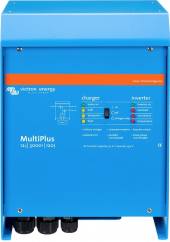
1. I have a Victron 3000 MultiPlus. 12v/50Amp/3000
2. Wire between Battery and Inverter is 4/0
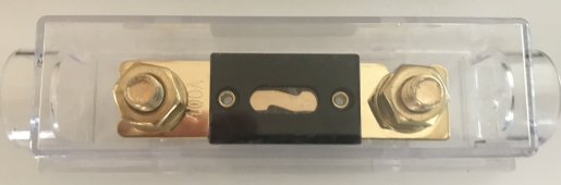
3. The fuse size is 350Amp
4. 3- Battle Burn 12V Battery at 100Amp each
Load: The fallowing Items is intended only for use one Item at a time for a load, witch I have not been able to use.
1. Water Heater Spec. 120v / 12Amp/ 1500w. it actually runs at 1712-1714w= Wire size 16AWG ?
2. Oven: 120v/ 15Amp/ 1800w= Wire size 14 AWG
3. Induction Stove Top: 120v/ 15Amp/ 2000w each burner. Max Load 4000w=Wire size 14AWG
4. Fridge: 120v/ 5Amp /50w
5. TV: 120v/ 2Amp /50w
My electrical wirrering was done with 14AWG. My intention with using any of my Appliances is base on the wire size, the circuit breaker and the fuse size. I have a 20A circuit breaker for the Oven and one for the Induction Stove top. I also have a circuit breaker for one line that will be feeding my Tv, Fridge and Water heater only when TV is not on.
My Water Heater is a 12Amp, My Fridge is 5Amps and my TV is 2Amps Just making sure that I’m not pulling more Amps on this line, more then intended- 15 to 18 Amps. So if my electrical is done correctly I think I am good to go without worrying about burning any wire. So the fuse should not be heating up to a red state, but then again I am not 100% correct on the way I set up my electrical. Sofa I’ve been living in my Van for a Month and a few days. Nothing going wrong in except to the fuse issue. Please help, Thank you.
Ps. 14AWG can handle up to 20Amps, is this true?
Jose.
@JMR53
It is usually best to start your own thread to solve a problem.
But I will try to help…
To start, we need to know all the details on your system.
System:
What inverter are you using?
What size of wires between batteries and inverter?
What type of fuse is heating up?
What battery capacity do you have?
Load
How many watts is the big load (water heater) using?
How much other load is on your system?
Other, do you have any other pieces of equipment installed that can help troubleshoot? Smartshunt? Cerbo? Clamp on Multimeter that reads amps?
My guess is you may be overloading your system with the water heater. But we need to figure it out first.


")