diy solar

diy solar

Victron Smart Shunt Not Measuring Charge Current?

Alphabavo

New Member
Joined
Feb 14, 2021
Messages
57
Howdy, All!

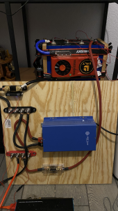
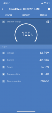
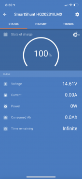
I've been working on building a small system, just to get my feet wet before I go all in. I have everything working so far, with the exception of my Victron Smart Shunt. The shunt measures everything except the charging current. I can watch the battery voltage increase slowly as it charges on the monitor, but there is no corresponding indication of current flow, and the historical tab shows 0 historical charge current. I have it installed as directed, as far as I can tell, and will include pictures. Thoughts?


tempImageF2uG6H.png
 
1. The shunt should be after the bms
2. Most fuse on the positive side.
3. Your $1 ANL fuse and holder is junk. Get a decent one.
 
Found a ~2v drop across the BMS. Connecting the charger direct to the shunt eliminates the problem, but I don’t know the mechanics of why…
 
I will be upgrading to a better breaker to protect the system shortly, this is just to make sure everything works before I build out something larger.
 
So I rearranged it as you suggested, the shunt no longer measures charge current and the charger drops into float mode. When I had the shunt place before the BMS and had the charger wired directly to the shunt, it worked fine. What would cause this?
 
What would cause this?
I expect a need to fully understand what is happening in the citcuit. Its really useful to carry out a little background reading on electric circuits. Internet search engines can help here.

I think the main confusion is that the BMS is regarded as a circuit component, instead, you need to consider the { cells and the connected BMS assembly } to be the 'battery'. Nothing else should be connected inside this 'battery'

The shunt is inserted in the negative path from the 'battery' to the negative buss bar.

The main protective fuse for the battery is placed as close as practical to the battery positive connection, the cable from the fuse connects to the positive buss bar.

Everything else, chargers and loads, are connected to the buss bars.

Victron tried to help by providing instructions with the smart shunt. The battery in this illustration, if lithium type , would have the BMS inside the grey box.
smart shunt.jpg

Mike
 
Last edited:
So I rearranged it as you suggested, the shunt no longer measures charge current and the charger drops into float mode. When I had the shunt place before the BMS and had the charger wired directly to the shunt, it worked fine. What would cause this?
The Charger and Loads negative need to be connected together to the shunt. The shunt measures current that goes through it.
Charger---|
Loads-----|----Shunt---BMS---Battery
 
...
Ok, I don’t see the cells in the picture at all...

the BMS is NOT supposed to be connected to a bussbar, it should be the primary connection to the cells. It looks like you are connecting to the charger, and the bussbar...

Same with the shunt sense lead, it goes directly to the cells... not a bussbar.
 
The blue wire terminal on the BMS should be labeled "B-" and that terminal should be connected directly to the battery cells.

Shunt connects to the black wire "P-" terminal and then your negative bus bar connects to the shunt. Like this.
IMG_2848 (1).jpg
 
Last edited:
Ok, so I've set it up as you guys have recommended and the shunt still doesn't measure any charging current, it also keeps the charger in float mode without allowing it to bulk charge.


If I place the shunt before the BMS and connect the charger directly to it (bypassing the BMS for charging) it measures the current. The ~2V drop across the BMS is still present.
 

Attachments

  • tempImage1mvdSi.png
    tempImage1mvdSi.png
    1,007.3 KB · Views: 41
You still have the shunt sense conductor on the positive bussbar... it should be on the battery main positive.
 
Ok, so I've set it up as you guys have recommended and the shunt still doesn't measure any charging current, it also keeps the charger in float mode without allowing it to bulk charge.


If I place the shunt before the BMS and connect the charger directly to it (bypassing the BMS for charging) it measures the current. The ~2V drop across the BMS is still present.
2V Vdrops measured between what point to what point? Between P- and B-? Also, the Vdrops is measured when you running the inverter and the loads?
 
The Vdrops should be in mV range. Did you try resetting the BMS? It sounds like the MOSFET's in the BMS are not fully turned on.
 
I don’t have any Vdrop on any of my batteries at the BMS... I think you should start there. Get a new bms...

Maybe clean the lugs and terminals and see if the drop vanishes.
 
The Vdrops should be in mV range. Did you try resetting the BMS? It sounds like the MOSFET's in the BMS are not fully turned on.
Shorting across the BMS P-& B- terminals will kick the charger on and start current flow....
 
When shorting lead is removed…
 

Attachments

  • 04CA74F0-4E3E-4BEB-90D9-74C0D4A0A580.png
    04CA74F0-4E3E-4BEB-90D9-74C0D4A0A580.png
    274.3 KB · Views: 5
The switched MOSFET's are connected between B- and P- so when you short the B- to P- the switched MOSFETs are bypassed that is why you get the current to flow, then when you remove the jumper the current stops flowing because the switched MOSFET's are not turned on by the BMS circuit.
I do not know which DALY BMS you have, but here is the link showing how to reset the Smart DALY BMS.
 
Back
Top