diy solar

diy solar

Victron Smartsolar Charger Remote On/Off

You're making it harder than it actually is. The remote is hardware not software. On the bottom right is a small connection with a jumper between the two. This is from the manual


The simplest way is "a". Just remove the jumper and connect wires to the two terminals from your relay. You don't need to supply 12V. If you want to supply 12 volts from your relay use "b".
Will method "b" work with a 48V nominal battery system? In other words if +48V is applied to the right remote on/off terminal on my Victron Smartsolar will it switch on, or will it fry/smoke/die a horrible twisted sucking death?
 
Bumping a not yet ancient thread... but I read conflicting reports in here of the trigger voltage on the ve direct RX pin. >=6v? >=3v?

I'm monitoring my BMS and 75/15 MPPT with an arduino and despite having a BMV712 sending voltage (and temp) data to the 75/15 over Ve smart networking, I've found it misses its mark plenty. Wondering if I could connect my RX pin and write high/low from the arduino to control charging. This obviously won't work if 5v doesn't satisfy the voltage requirement of the RX pin.

Has anyone gotten this working in any capacity? If yes, does it do the same thing as simply flipping the "Enable Charger" toggle off in the Victron app?

Wish I could figure out bidirectional communication with Victron products, but at present I've been using the text output they spit out every second for read-only. Can't really find any examples on the hex protocol, but it'd sure be sweet to:

1) Read BMS - oh no a cell is exceeding the desired 3.45v and the rest are a little bit behind
2) Tell the Victron to drop max charging current from 15 to something lower and re-assess
3) Keep doing that, dropping charge current so that the BMS can balance properly and all cells reach desired voltage

I'll settle for shutting it off via RX pin if something gets wonky before float, though. Would be sweet if the arduino could do all of this and not rely on a 12v relay.
 
Howdy,

The Ve Direct Protocol is well documented.

Go to...

Victron Ve.direct Protocol FAQ

Download the Data Communication white paper for the complete hardware specs and which Victron units are supported.

Then download the VE.Direct protocol document. It's a very well documented command by command summary. Everything you need is there.

Then click on Open Source, and you'll find a ton of Arduino, Raspberry Pi, and PC projects and articles.

Enjoy, as the Ve Direct Protocol works great and is a great way to blow off a snowy day or two.....
Yeah, the text protocol is easy to read and utilize - that's what all of the arduino and similar projects are using. Can't find much using the hex-ascii, think I stumbled upon a forum result for this and it was obviously much more involved than listening to it shouting in to the void. And I believe I read that once you send a hex command it switches to hex mode, no text protocol shouting in to the void, so you're committed then to a much more complex way of reading data, just to write something like "stop charging"
 
Your observations are correct. But once you've written the routine to 'build' a message (or decode a msg), then the next 30 commands are a piece of cake.

The hex protocol is worth the effort because everything is checksumed so the message is now checked for errors. 'stop charging' in a noisy environment doesn't become a 'stop charging'.

Overall worth the effort, because you also plan on doing things like changing charge rates.

Enjoy...
 
All the code to build and decode messages are in this well written library.

Arduino VE.Direct library based on Victron's reference implementation

Check out the 'example' code.
yeah I actually posted an issue on that github a couple days ago. Falls apart on software serial, nothing really new there. Just completed a sketch that works fine with software serial and allows enabling/disabling charging. Works great for that purpose, the read is almost as perfect. The more values you request the more error prone it becomes - ex: I can request one value and get that back every second, but if I request 5 values and log timestamps, some begin to not update for upwards of 20 seconds. That's not the end of the world, but doing a calculation between battery voltage and charge current, and then comparing to the "panel wattage" variable would be squirrely if panel wattage hadn't updated for 20 seconds.

Thankfully I just need charger state, panel wattage, and panel voltage. The rest can come more reliably from the BMS. I'll have to figure out how to set charge amps. In any event being able to enable and disable charging was worth the evening's efforts.

Sadly the controller still shouts in to the void while also responding to commands for specific values. I figured that'd quit when in "hex mode" but there's still a lot to ignore, and that contributes to the slipping of value updates.
 
This is working well, would highly recommend anyone trying to remote enable/disable over VE direct to just spend a couple of bucks on a microcontroller. Can add some $0.50 temp sensors to give it more purpose if you don't have a smart bms to also integrate with. I had this old display laying around so I figured why not-even though I have a perfectly good serial monitor and won't be using the screen in any of my setups.

This particular project is using a BlueSolar MPPT so it lacks bluetooth communication. The victron dongle I bought years ago was the older version so it doesn't support VE Smart networking :cautious: - thus it's only good for using the victron app, not communicating with a smart battery sense or BMV.

This MPPT is actually in a ventilated (temp controller module on load output to exhaust fan) small pelican case with panel mount connections for PV and battery. It charges up several of my portable packs that I didn't want to dedicate an MPPT to (I do have two big batteries that do have their own SmartSolar ccs though). The problem in using it like this is that the packs have different wiring and connections, so the resistance is different. Meaning if I set absorption to 14.2v (which on one portable pack nails 13.8v actual on the nose), it over or undershoots on other packs.

All of my batteries use chinese smart bms units so all I have to do is install 3 pin aviation connectors on the portable packs, and one on the portable MPPT box with the microcontroller. Can do my own double-safety temperature cutoff based on BMS temps and set my absorption voltages to a higher number than I'd prefer but that still won't exceed 3.65vpc on any pack. When the pack's BMS says a cell has hit the max I want it to go to the MPPT is disabled - future plans to try and taper max charge current to let bms balance easier and get every cell to where I want it.

So yea that's about $5 in parts to make a Victron mppt smarter than it already was and respect cell voltages as reported by BMS. My big setups that have dedicated MPPTs are running SmartSolar offerings and already doing all of the above with their own microcontrollers, as they still have ve direct ports. The bluetooth still works on those despite being talked to through ve direct, as does smart networking (those have BMVs transmitting temp and more accurate voltage).
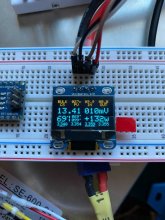
Image from iOS.jpg

another cool thing is being able to differentiate what's going in versus what's going out, since I know the MPPT charge current. That's a feature that I wish the BMV could accomplish, because if you're using 50w and charging at 50w you'll simply see 0 and have to flip to MPPT in app to see what's really happening there. The smart bms' also have the same limitation as the BMV in this respect.

But anyway, '09.9 In' is what the MPPT is charging at. '00.0 Out' is where the actual discharge current is calculated based on MPPT in and BMS current reading. +132w is the net going either in or out. Large underline vs small underline on cell voltages indicates min/max, delta, temp, battery voltage which flips every 5 seconds to show SOC%. Pretty cool. I'll put it on github some day.
 
Back
Top