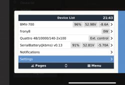
After MUCH hassle, i finally made it working ?
It turned out to be a series of alignments in order to make it work on the JK BMS.
First things first, many thanks
@Louisvdw for all your effort. The code works perfectly! ?
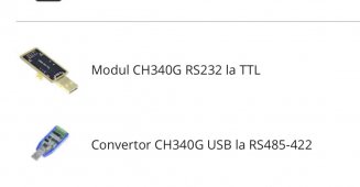
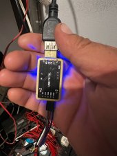
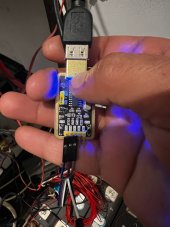
So, turns out the JK standard is a bit of strange one and it CAN be done with a SUB-TTL adapter, but not all are made equal and it must be on that supports 3.3v.
I've also figured out a way to test where the issues might be:
1. install software as descried in the how to in git (I would go via ssh, even on mobile client it works pretty good).
2. have laptop or mobile at the ready to run some commands
3. connect wiring between bms and GX (or Pi, but I have GX, use one of the 2 free USB ports, I have not tested the 3rd which is kind of separate from the other 2)
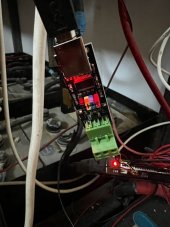
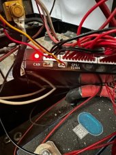
- on JK BMS, use the GPS port (2nd port from the left) and only the first 3pins (again from left) GND RX, TX (order is important for next step)
- on adapter side match GND and REVERSE cables RX and TX (RX from BMS goes to TX from adapter and TX from BMS to RX on adapter, this is how all serial works - as a check you've done this correctly, your adapter might have some leds that BOTH will flash, if only TX flashed, they could be TX-TX and RX-RX, so check cabling).
4. if you're lucky, it might just work, if not, here's how to troubleshoot where the fault might be
5. using said laptop/mobile at point 2, open a terminal emulator (on iOS i used Terminus, windows I used Putty, but ANY will work)
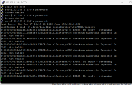
- login as root as per procedure
- fist run command
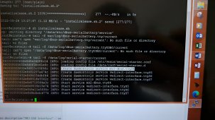
tail -f /data/log/serial-starter/current - this will check that USB is recognized by GX/Pi. It should say something like INFO: Start Service bla bla bla (or doing something in general, it works), if nothing appears ending with ttyUSB0 (might be 1,2... instead of 0) than your adapter is not recognized - try different USB port/cable/replace adapter, if it works move to next step
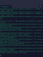
- second run command
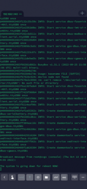
tail -f /data/log/dbus-serialbattery.ttyUSB0/current - this will check if your adapter sees the battery and/or some other errors (
@Louisvdw the second command is not presented with tail -f command and initially i used sfpt to check logs, later decided to try the ssh command and it also worked, perhaps you can update the page on GIT?)
I tried 5 adapters until it worked (well, 4 technically, but you'll why I said 5...).
In some posts above you can see that i ordered. Including a USB-TTL adapter, which initially didn't work. As I troubleshooted and started to doubt my (mhhmmm awesome) cabling work, I started tested with a multi-meter. And I noticed that while connecting the bms to the adapter, the voltage was ~1.2v, while the adapter was putting 5v. When I checked the BMS without any cabling it was ~2.3/2.4v so I figured it might work on 1.5v as standard. After some googling, i found there is no standard for 1.5 and most are 3.3, 5 and 12v. After looking at this USB-TTL adapter, I noticed it has a jumper between 3.3v lead and 5v (and it was bridging the 5v) so I moved it to 3.3 and it freaking stared to work!!
The other ones are strictly 5v, but i will try to find another adapter with 3.3 and test. My theory is that it will accept any RS485, but as long as it's 3.3v.
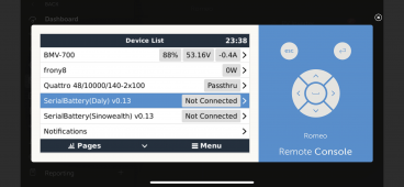
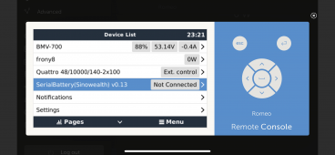
This is pretty much it! As advertised, Louis's code works pretty good and you will no longer have to rely on the shunt (which ready differently than the BMS and shuts off your battery when least expect it
")
)
I do have some issues with CRC (see putty export), but it seems to work on GX without issue.