diy solar

diy solar

Victron VenusOS driver for serial connected BMS - JBD / Daly / ANT / JKBMS / Heltec / Renogy / Tian / ECS

It looks like the ttyUSB0 does not work from time to time...
If you are running this on a Raspberry Pi then make sure you have a large enough power supply (> 2.5A). Sounds like the USB interface might be dropping and this is normally a power issue. Do you use a USB hub?
VenusGX and CerboGX normally would not have the same issue as it get it power directly from the battery.

If you switch to VenusOS V2.73 does that improve? If not also cheak you data connection cable.
I use a 10A DC/DC converter where 2 Raspis are connected. The 2nd Raspi works without any problems and has no trottling messages in the log. Up to version ~36 I didn't have these problems. This only started with the update to ~38. But I can test if it works better with version 2.73.
 
Did anyone try to use latest version of JK BMS? I just got one in the mail today and it looks different. Previous version had "CAN" port and "GPS/RS485" port. This one has "CAN/RS485", "GPS" and two extra ports with chineese labels only. One of those will be for the LCD I guess. Anyway, does it mean we should use CAN/RS485 this time? It also has different port size. Previously both ports were the same. This time the CAN/RS485 is smaller, 3 pins, probably JST GH?
 
Did anyone try to use latest version of JK BMS? I just got one in the mail today and it looks different. Previous version had "CAN" port and "GPS/RS485" port. This one has "CAN/RS485", "GPS" and two extra ports with chineese labels only. One of those will be for the LCD I guess. Anyway, does it mean we should use CAN/RS485 this time? It also has different port size. Previously both ports were the same. This time the CAN/RS485 is smaller, 3 pins, probably JST GH?

Could you share a picture? It seems there are a few different versions popping up these days...

Edit:

Sb1a2b1fef691468eb480bd801d39dc164.jpg

Now I need to find out what the "Heat Function" does... Mine are still in transit; can't wait to open one up to see what the changes are.

Edit 2: apparently the heat function is to be used in conjunction with a heating film, probably to heat the batteries. This would negate the need for an external thermostat...
 
Last edited:
  • Like
Reactions: Dzl
Yes, looks like on your picture. Just weird that the left port is labeled RS485, but description says it's the second one?
 
I have now downgraded and haven't had any problems since... It seems to be a problem with firmware 2.80.
I would suggest you post this to the V2.80~38 thead on Victron Modification forum. It might be a new issue
 
Could you share a picture? It seems there are a few different versions popping up these days...

Edit:

Sb1a2b1fef691468eb480bd801d39dc164.jpg

Now I need to find out what the "Heat Function" does... Mine are still in transit; can't wait to open one up to see what the changes are.

Edit 2: apparently the heat function is to be used in conjunction with a heating film, probably to heat the batteries. This would negate the need for an external thermostat...
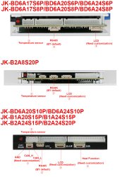
① This is the default RS485 interface, but it is only used when it is linked to specific equipment in China. If you buy an external RS485 module, you need to connect to ② this interface. At the same time, for the current BMS, we b2a24s20p have customized the CANbus function. After communicating with a technician of the forum, it is planned to open the firmware, but it takes time to debug.
 
① This is the default RS485 interface, but it is only used when it is linked to specific equipment in China. If you buy an external RS485 module, you need to connect to ② this interface. At the same time, for the current BMS, we b2a24s20p have customized the CANbus function. After communicating with a technician of the forum, it is planned to open the firmware, but it takes time to debug.
①:CANBUS interface (At present, only jk-B2A24S20P can customize the CANBUS function)
②:RS485 interface(At present, all JK BMS are configured with RS485 function by default)
③:LCD interface(Please check whether BMS has LCD interface before purchasing. If there is no interface, LCD cannot be used)
④:Heat Function interface(At present, the heating function customized by customers can be accepted, MOQ50pcs)
⑤:Temperature sensor
IMG_7320.jpg
 
Is victron's USB-VE.Direct the correct cable to connect Cerbo GX to JK BMS? I'm still trying to make it work, but it always fails with
Code:
WARNING:SerialBattery:Testing Jkbms
ERROR:SerialBattery:>>> ERROR: No reply - returning
BMS is JK-B2A24S20P, HW ver 8.X SW ver 8.20G

I'm connecting GND, TX, RX (no Vbat). Not sure about pinout in VE.Direct, but I've tried all possible combinations several times already.
I've tested the cable with MPPT controller and cable works fine
I've connected BMS to ESP32 with https://github.com/syssi/esphome-jk-bms and was able to get data in home assistant, so BMS UART works fine too.

Any idea what could be wrong?
 
I'm connecting GND, TX, RX (no Vbat).
The Victron cables like the USB->VE.Direct and USB->VE.RS485 are isolated cables (meaning power from the one side cannot flow to the other side as a safety feature). So you need to power them on both the USB side (always done as part of USB protocol) and the BMS side(you will have to connect the Vbat positive as well).
 
I was afraid to connect it as it is 55 V and I was not able to find maximum allowed voltage for VE.Direct Power+ pin. So, 55 V is still safe? It's a bit higher than what I've seen previously on data ports and I don't want to damage anything.
 
I was afraid to connect it as it is 55 V and I was not able to find maximum allowed voltage for VE.Direct Power+ pin. So, 55 V is still safe? It's a bit higher than what I've seen previously on data ports and I don't want to damage anything.
No 55V is not safe (I see you are talking about the battery voltage here). RS485 normally run between -7V and 12V, but 5V is most often used.
The RS485 port would have either 4 pins or 2 pins. The 4 pins would be the same as your cable (GND, V, Rx, Tx) and you can just use that V. If it is only 2 pins (Rx, Tx) you will need to use the command GND and a 5V from somewhere (buck converter for example), but the BMS should have an internal power of 5V or 12V. Check the pins of the connectors with a mutimeter
 
So I wonder how ppl connect JK BMS to Cerbo or RPi. As JK BMS's port has TTL UART logic with 4 pins - GND, TX, RX, but the fourth power pin is actually Vbat, not +5V. It doesn't feel safe to use non-isolated cable (for case BMS turns off discharge).

With the newer JK BMS version that has port for LCD connection, there could be a pin with 5V, but the pre-LCD version seem to have only Vbat. I guess that's what that JK's TTL->RS485 converter box does
 
All SBMS0 owners, I'm going to be sending off my SBMS0 to @Louisvdw once I get an address. If you feel like donating to help me replace my SBMS0, please shoot me a PM and I can send you my paypal address if you want to chip in. I'll take half the donations (to recoup my costs for the SBMS0) and the other half I'll send to Louis.
Any news on SBMS0 integration with VenusOS driver?
 
Back
Top