diy solar

diy solar

Voltage spike read on SCC, inverter shutoff, voltage drop and inverter back on

So, I uploaded the battery config that was suggested above. Seems to have saved. That said on my battery monitoring main screen the max and min voltages are something different. Is this just like the max and min of the day?

Yes, min and max voltage for the duration of the monitoring session.
What does 'something different' mean? Different from your charge voltage settings?

The battery voltage displayed on the controller or recorded in the log, is simply what the controller is reading from the battery. Mostly it's not that accurate either, as mentioned it measures your battery voltage with the charge current on top. It's most accurate on float or when charging is terminated. Your battery will always settle back some at rest.

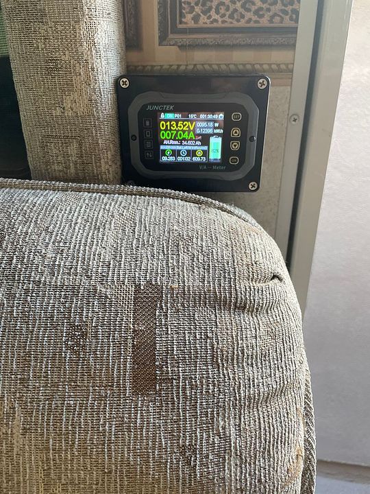
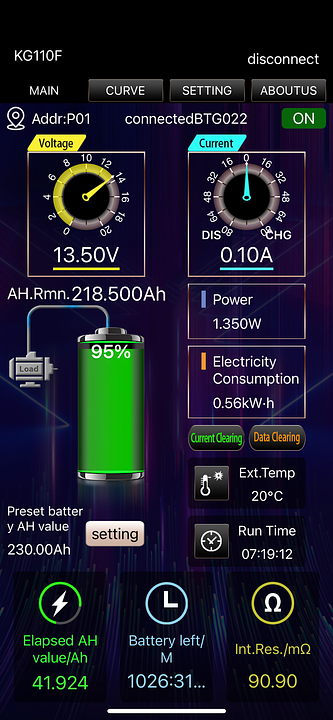
My pack is sitting at 13.3V and bms says it's at 98% full - 228Ah of 230 left.

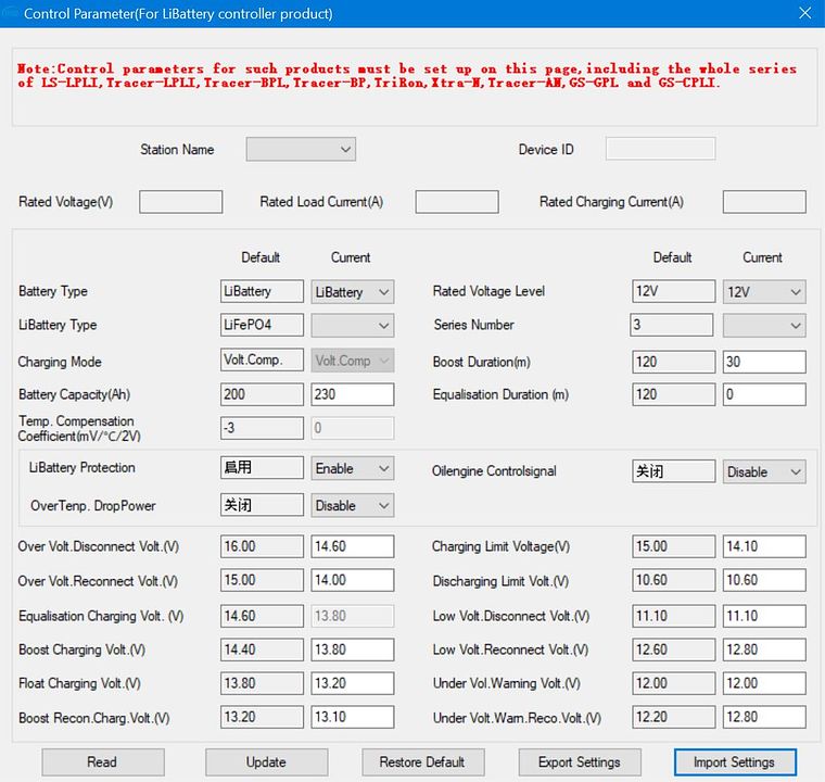
My system is installed in a Winnebago motorhome, which sits parked mostly, and it can get rather warm here in southern CA. So my 'in storage' parameters are below - any loads bring SOC down to about 60-70% and will just maintain or float there. Tracer has a default re-boost every 7 days. The boost duration is a little longer because it's a low 13.8V, which gives it some time to feed more amps in before it floats again.
If we're going to be using the coach I load the control parameters from above.


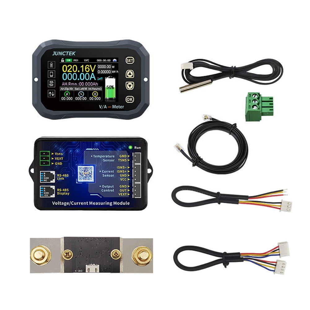
Having a shunt meter makes all the difference - it measures amps in and out and gives an accurate SOC:

 
I noticed that the load is switching on sometime during the night. I think this is some setting for grid power? Like on the epever controllers the main display shows solar panels arrows and battery when charging but if you press enter the arrows also go to the light bulb with a W in it. Maybe I am reading too much into it but with my setup I don't think this should ever be on.

If you're not using the load you can manually switch it off with the program in the monitoring window.
You can also press load and the off button and turn it off with the controller buttons.
I have notice the load will turn on when powering up the controller. If nothing is connected to the terminals then no energy is used either.

Some of the newer controllers have done away with the load terminals. Most people don't use them anyway.
 
@Browneye
How do like that JUNCTEK meter so far? I am thinking about getting one to play with. Model #?

I was rather skeptical for the introductory discount price of $25. I think they sell them on aliexpress for like $45, and they have split out the display as a separate purchase if you want, as the BT app is just excellent - image below. I like the display for a quick glance on battery state, and current consumption or charge current.

I bought a 'project box' for the display as it is a flush mount setup, and didn't want to cut a 2x3 hole in any of my panels in case it just didn't work. But it has been really good, I like it a lot.

The smart shunt is well made, come in 100 200 and 500A sizes. Super easy to setup - it has a base module that plugs into the shunt, and it needs a positive side lead for power, then a 20' RS type phone cable to connect the display. It does have some switching capability if you want to use it for relays to do stuff- shut down, start, turn off or on etc. and a temp probe. I don't use the switching features.

Two things I mentioned to the rep on it - the temp display is called 'ext temp' which should be 'battery temp' and it's fixed at Celsius - would like to see an option to change it to Fahrenheit. They are supposed to make these changes on the next firmware release. I don't know when or how to update it.

It also took me some playing around with it to figure out how to calibrate it - it shows total Ah, Ah available, and the SOC as a percent meter. Which is cool, but how to get it to be accurate? When your battery is fully charged you set the total amps and the percent charge at 100% and then it keeps track of amps in and out. This part works just excellent. Idle consumption is about 10mA thru the shunt.

I think if you contact the rep he'll give you a forum discount coupon. Took about a month to arrive.

Smartphone app display. All of the values are configurable in the app and on the display.


78abc50b-2e02-436a-84bc-c1731ee48f47.ffee4267402a0134d674574432a98105.jpeg
 
Manual from your link:
https://www.epever.com/wp-content/uploads/2021/05/Tracer-AN-SMS-EL-V1.0.pdf

The manual has a warning on page 19 about BMS limitations.
I do not see that on page 19. There is no communication between SCC and the battery BMS so I cannot see why that will be any conflict.
I think this portion of the discussion needs to be reopened.

The linked manual for the OP's controller does contain a warning on page 19, as I stated in post 12 of this thread.
The post has been edited to remove the information in question, but should not have been removed.
I was led to believe PCM is not a synonym for BMS. I suspect it is.

The term PCM is used on pages 18 and 19 where we would have expected to see the term BMS.
Page 18:
"The following rules must be observed when modifying the parameter values in User for lithium battery.
Ⅰ. Over Voltage Disconnect Voltage>Over charging protection voltage(Protection Circuit Modules(PCM))+0.2V※;"

Page 19:
solarhelpe 101.PNG


There is no reason this subject should be eliminated as a possible cause. The manufacturer clearly addresses the issue and so should the consumer. By considering the possibility we may discover that the battery BMS or PCM has some influence in the OP's issue.
 
They are talking about how accurate the BMS shutdown points are.
PCM = Protection Circuit Modules.
EPVER itself does not show published accuracy of their metering circuits either, so their protection shutdown point accuracy cannot be determined.
 
Back
Top