


Please help with sensible settings. I connected the balancing wires, but am afraid of hooking up to the solar panels and over/under charging the batteries, which could ruin them. After finally getting an Android app (MaYi-BMS) connected over bluetooth, I followed the seller's scant instructions and pressed the FE-LI PARAM button to set it to LifePO4 chemistry. But most of the values seemed to remain inappropriate for the 3.2V cells I have.
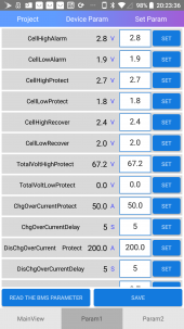
Currently set on my 8-20S 400A BMS:
(no heatsink, no LCD)
Project Device Param
Cell High Alarm 3.65V
Cell Low Alarm 2.8V
Cell High Protect 3.6V
Cell Low Protect 2.6V
Cell High Recover 3.4V
Cell Low Recover 3.0V
Total High Protect 87.6 V
Total Volt Low Protect 0v
Charge Over Current Prot 50.0A
Charge Over Current Delay 5S
Discharge Over Current Prot 300.0A
Discharge Over Current Delay 5S
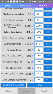
max balance limit volt 3.6V
start balancing volt 3.4V
cell diff value to start bal 0.002V
bal current value 200MA
system reference voltage 3.0V
current sensor range 540.0A
pre-charge current 30A
short circuit current value 700A
short circuit delay time 700US
auto standby time 180S
total volt ref value 3505N
actual connected cell number 8S
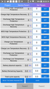
charge high temp protection 60C
charge high temp recovery 55C
discharge high temp protection 60C
discharge high temp protection 55C
MOS high temp protection 75C 75C
MOS high temp recovery 70C 70C
charge low temp protection -2C
charge low temp recovery 3C
discharge low temp protection -10C
discharge low temp recovery -5C
battery physical capacity 310.0AH
battery remaining capacity 0.0 AH
total cycle capacity 0.0 ah
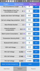
tire circumference length 1000M
pulse no of one tire circum length 23N
system shut down cell volt 2.4V
cell unit volt gap protect 1.0V
slave module number 65535 N
internal resistance compensation 0.0 MR
silent current consumption 3.5MA
temperature sensing shield 0 N
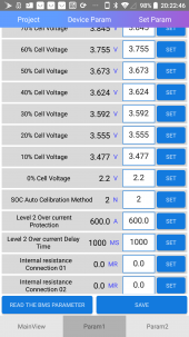
100% cell voltage 3.4V
90% cell voltage 4.053V
80% cell voltage 3.946V
70% cell voltage 3.845V
60% cell voltage 3.755V
50% cell voltage 3.637V
40% cell voltage 3.624V
30% cell voltage 3.592V
20% cell voltage 3.555V
10% cell voltage 3.477V
0% cell voltage 3.1
SOC Auto Calibration Method 2 N
Level 2 Over current Protection 600.0 A
Level 2 Over current Delay Time 1000.0 MS
Internal Resistance Connection 01 0.0 MR
.
.
.
Internal Resistance Connection 24 0.0 MR
The only ones I set so far were battery physical capacity and actual connected cell number.
Many fields seem meant for some other kind of battery cell with difference nominal voltage (18650 maybe?), or illogical (non-sequential % cell voltage).
Generally I don't know what many of these mean/how they work. Is there a good example of these BMS parameters somewhere configured for Pristmatic 3.2V LifePO4? (Could be a different Ah) A manual or guide that covers some of these settings?
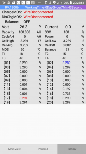
Also, how can I tell if my BMS model linked above is active or passive(stupidly wastes power discharging the highest-voltage cells till the others catch up)?
Currently set on my 8-20S 400A BMS:
(no heatsink, no LCD)
Project Device Param
Cell High Alarm 3.65V
Cell Low Alarm 2.8V
Cell High Protect 3.6V
Cell Low Protect 2.6V
Cell High Recover 3.4V
Cell Low Recover 3.0V
Total High Protect 87.6 V
Total Volt Low Protect 0v
Charge Over Current Prot 50.0A
Charge Over Current Delay 5S
Discharge Over Current Prot 300.0A
Discharge Over Current Delay 5S
max balance limit volt 3.6V
start balancing volt 3.4V
cell diff value to start bal 0.002V
bal current value 200MA
system reference voltage 3.0V
current sensor range 540.0A
pre-charge current 30A
short circuit current value 700A
short circuit delay time 700US
auto standby time 180S
total volt ref value 3505N
actual connected cell number 8S
charge high temp protection 60C
charge high temp recovery 55C
discharge high temp protection 60C
discharge high temp protection 55C
MOS high temp protection 75C 75C
MOS high temp recovery 70C 70C
charge low temp protection -2C
charge low temp recovery 3C
discharge low temp protection -10C
discharge low temp recovery -5C
battery physical capacity 310.0AH
battery remaining capacity 0.0 AH
total cycle capacity 0.0 ah
tire circumference length 1000M
pulse no of one tire circum length 23N
system shut down cell volt 2.4V
cell unit volt gap protect 1.0V
slave module number 65535 N
internal resistance compensation 0.0 MR
silent current consumption 3.5MA
temperature sensing shield 0 N
100% cell voltage 3.4V
90% cell voltage 4.053V
80% cell voltage 3.946V
70% cell voltage 3.845V
60% cell voltage 3.755V
50% cell voltage 3.637V
40% cell voltage 3.624V
30% cell voltage 3.592V
20% cell voltage 3.555V
10% cell voltage 3.477V
0% cell voltage 3.1
SOC Auto Calibration Method 2 N
Level 2 Over current Protection 600.0 A
Level 2 Over current Delay Time 1000.0 MS
Internal Resistance Connection 01 0.0 MR
.
.
.
Internal Resistance Connection 24 0.0 MR
The only ones I set so far were battery physical capacity and actual connected cell number.
Many fields seem meant for some other kind of battery cell with difference nominal voltage (18650 maybe?), or illogical (non-sequential % cell voltage).
Generally I don't know what many of these mean/how they work. Is there a good example of these BMS parameters somewhere configured for Pristmatic 3.2V LifePO4? (Could be a different Ah) A manual or guide that covers some of these settings?
Also, how can I tell if my BMS model linked above is active or passive(stupidly wastes power discharging the highest-voltage cells till the others catch up)?
Attachments
-
 Screenshot_20210519-201948.png234.2 KB · Views: 15
 -
 Screenshot_20210519-202249.png272 KB · Views: 15
 -
 Screenshot_20210519-202310.png265.9 KB · Views: 11
 -
 Screenshot_20210519-202322.png280.3 KB · Views: 9
 -
 Screenshot_20210519-202331.png267.5 KB · Views: 9
 -
 Screenshot_20210519-202341.png233.6 KB · Views: 8
 -
 Screenshot_20210519-202359.png204.3 KB · Views: 8
 -
 Screenshot_20210519-203400.png297.4 KB · Views: 14