meetyg
Solar Enthusiast
- Joined
- Jun 4, 2021
- Messages
- 1,089
Hi there,
I just received this 24v 8A Lifepo4 charger that I got from Aliexpress, that will be used for a 24v 40Ah DIY Lifepo4 pack I'm building.
This pack will be a replacement for SLA batteries used in a small mobility scooter.
The current setup uses a small 24v 2A SLA charger to charge two 12v 30Ah batteries in series.
Anyways, I needed to get an appropriate charger for the new Lifepo4 setup, so I got this one:

 www.aliexpress.com
While it outputs 29.2v which is 3.65v per cell for an 8S battery, I don't want to go that high in my setup. I'm planning on 28.4v or 3.55v per cell.
So I saw this picture on the item description and noticed that there some POTS on the PCB. That made me think that maybe I could set it to a lower voltage myself.
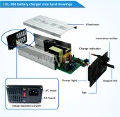
I could have asked the seller if it supports changing the voltage, or just asking them to do it, but it was on Black Friday sale and I didn't want to delay the order.
So now that I received it (unfortunately before the Lifepo4 cells) I opened up the output side if the charger, and long behold there is a Pot labeled VR.
So I started to play with it and it does change the output voltage!
If I recall correctly turning counter clockwise reduces the voltage.
The problem is that it's not that accessible.
I didn't want to take the PCB out, because someparts are glued, and there are some FETS attached to the walls of the enclosure with screws (and probably have some thermal past on them too).
But I was able to turn the Pot slightly with a small flathead "jeweler's" screwdriver.
There are additional Pots deeper inside the PCB, which are really inaccessible unless you pull out the PCB. I think those are for the CV cutoff, which is 5% of the amperage by factory.
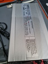
Here are some pics to help understand what I'm talking about (blue colored Pot right of the LEDs):
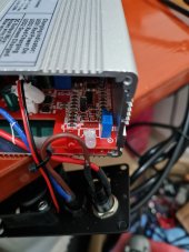
Just be careful when you try to turn the Pot, because other than the pot leads that are soldered to the PCB, it isn't held with anything else, and could bend/break the leads.
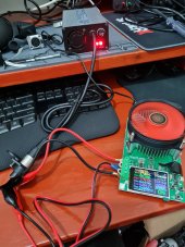
I also tried to do some testing using the DL24 battery capacity meter, set to Constant Current mode. But I wasn't able to test at 8A because the meter is limited to around 150w, and it stopped the test when I set more than around 5.5A.
But it looks like this charger really is a CC charger, as it dropped down the voltage a bit, each time I increased the amps.
As for the CV phase, I'm not sure how to test it with this equipment.
The internal fan kicks in when you exceed ~1A load, and stops when you thenload decreases from that.
I guess I will wait for the battery cells to arrive and test the charger fully when my 24v pack is all setup.
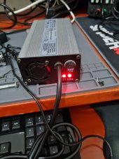
I hope this helps anyone who is looking for a Lifepo4 charger, that doesn't necessarily charge to 100% (for battery longevity).
Just a small note: This charger had a weird smell to it, as if a capacitor was blown, even before I started testing and fiddling with it.
But all the components inside look fine and new (as far as I could see without ripping it all apart). It also works fine as tested.
I suppose this smell might be from the manufacturing process, or from the white silicone/glue gunk they used to glue/mount some of the parts inside. I recall Will Prowse also mentioning a weird smell on one of his battery teardowns (not the ones that leaked), which had alot of glue inside too.
I just received this 24v 8A Lifepo4 charger that I got from Aliexpress, that will be used for a 24v 40Ah DIY Lifepo4 pack I'm building.
This pack will be a replacement for SLA batteries used in a small mobility scooter.
The current setup uses a small 24v 2A SLA charger to charge two 12v 30Ah batteries in series.
Anyways, I needed to get an appropriate charger for the new Lifepo4 setup, so I got this one:

34.97US $ 33% OFF|WATE 29.2V 8A Charger 24V LiFePO4 Battery Smart Charger Used for 8S 24V LiFePO4 aluminum case Battery pack Charger|Chargers| - AliExpress
Smarter Shopping, Better Living! Aliexpress.com
While it outputs 29.2v which is 3.65v per cell for an 8S battery, I don't want to go that high in my setup. I'm planning on 28.4v or 3.55v per cell.
So I saw this picture on the item description and noticed that there some POTS on the PCB. That made me think that maybe I could set it to a lower voltage myself.

I could have asked the seller if it supports changing the voltage, or just asking them to do it, but it was on Black Friday sale and I didn't want to delay the order.
So now that I received it (unfortunately before the Lifepo4 cells) I opened up the output side if the charger, and long behold there is a Pot labeled VR.
So I started to play with it and it does change the output voltage!
If I recall correctly turning counter clockwise reduces the voltage.
The problem is that it's not that accessible.
I didn't want to take the PCB out, because someparts are glued, and there are some FETS attached to the walls of the enclosure with screws (and probably have some thermal past on them too).
But I was able to turn the Pot slightly with a small flathead "jeweler's" screwdriver.
There are additional Pots deeper inside the PCB, which are really inaccessible unless you pull out the PCB. I think those are for the CV cutoff, which is 5% of the amperage by factory.
Here are some pics to help understand what I'm talking about (blue colored Pot right of the LEDs):


Just be careful when you try to turn the Pot, because other than the pot leads that are soldered to the PCB, it isn't held with anything else, and could bend/break the leads.
I also tried to do some testing using the DL24 battery capacity meter, set to Constant Current mode. But I wasn't able to test at 8A because the meter is limited to around 150w, and it stopped the test when I set more than around 5.5A.
But it looks like this charger really is a CC charger, as it dropped down the voltage a bit, each time I increased the amps.
As for the CV phase, I'm not sure how to test it with this equipment.
The internal fan kicks in when you exceed ~1A load, and stops when you thenload decreases from that.
I guess I will wait for the battery cells to arrive and test the charger fully when my 24v pack is all setup.


I hope this helps anyone who is looking for a Lifepo4 charger, that doesn't necessarily charge to 100% (for battery longevity).
Just a small note: This charger had a weird smell to it, as if a capacitor was blown, even before I started testing and fiddling with it.
But all the components inside look fine and new (as far as I could see without ripping it all apart). It also works fine as tested.
I suppose this smell might be from the manufacturing process, or from the white silicone/glue gunk they used to glue/mount some of the parts inside. I recall Will Prowse also mentioning a weird smell on one of his battery teardowns (not the ones that leaked), which had alot of glue inside too.


