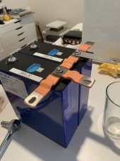
My 304ah cells arrived the other day. The only option were the welded stud option so that's what I went with. Since this is going to be installed in to a camper van, I opted to buy an extra set of flexible bus bars that I saw on @LithiumSolar youtube channel (
) to better handle the road vibrations. Might be overkill as my last van had rigid bars, but they weren't terribly expensive. They are 3mm thick instead of 2 mm thick as I will be running 12v. Since my 3000w inverter can pull up to 260 amps I wanted to upgrade.


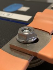
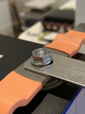
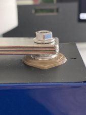
The bus bars aren't here yet, but as I was in the process of unboxing and inspecting the cells for damage (they were all fine) I had an "Oh crap" moment. I will be installing them in a 4p4s config, so I need to double up the busbars at the serial connection. The stock welded studs are only 10mm high so where I'm doubling up the bus bars for the serial connections they are going to be 6mm (+- a few fractions of a mm), I won't be able to get the nut all the way down on the stud. I took the stock bars to kind of simulate the new bars. I took three bars which is 6mm and put the nut down and there are about 2 of the 5 threads not catching anything:
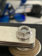
I'm curious if this is going to matter much with a flange nut. I went overboard with the bus bars, but in reality I will never pull that much from the inverter, but since the inverter can do it, I wanted to have the system ready for any draw it can handle.
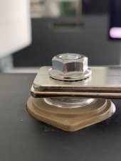
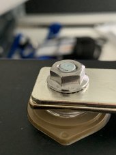
The stock bars are 40mm2 they can handle about 150 amps where as the upgraded bars are 60mm2 and should be able to handle 200amps and I planned on doubling up the serial connections between two cells. Now I'm wondering if I should just stick with the stock bars or a combination of the stock bars for the serial connections and the flexible bars for the parallel connections (3mm + 2mm of the stock bar but I can double up on them between two of the parallel cells). Here is a stack of 2 cells at 4mm. It just barely covers the stud so I figure 1 extra mm should be okay. I would cut down the length of stock bars for the serial connections and have enough were I could do a serial connection at each cell. I'm not really worried about flex at the parallel connections since the cells are narrowest at that point.
What are the forum's thoughts on this? I can do more testing once the flexible bars get here.
Thanks!


The bus bars aren't here yet, but as I was in the process of unboxing and inspecting the cells for damage (they were all fine) I had an "Oh crap" moment. I will be installing them in a 4p4s config, so I need to double up the busbars at the serial connection. The stock welded studs are only 10mm high so where I'm doubling up the bus bars for the serial connections they are going to be 6mm (+- a few fractions of a mm), I won't be able to get the nut all the way down on the stud. I took the stock bars to kind of simulate the new bars. I took three bars which is 6mm and put the nut down and there are about 2 of the 5 threads not catching anything:


I'm curious if this is going to matter much with a flange nut. I went overboard with the bus bars, but in reality I will never pull that much from the inverter, but since the inverter can do it, I wanted to have the system ready for any draw it can handle.
The stock bars are 40mm2 they can handle about 150 amps where as the upgraded bars are 60mm2 and should be able to handle 200amps and I planned on doubling up the serial connections between two cells. Now I'm wondering if I should just stick with the stock bars or a combination of the stock bars for the serial connections and the flexible bars for the parallel connections (3mm + 2mm of the stock bar but I can double up on them between two of the parallel cells). Here is a stack of 2 cells at 4mm. It just barely covers the stud so I figure 1 extra mm should be okay. I would cut down the length of stock bars for the serial connections and have enough were I could do a serial connection at each cell. I'm not really worried about flex at the parallel connections since the cells are narrowest at that point.


What are the forum's thoughts on this? I can do more testing once the flexible bars get here.
Thanks!


