diy solar

diy solar

What EMI filter do I need?

ctdctd

New Member
Joined
Dec 16, 2021
Messages
12
Hi,

I have two no-name budget chargers which I use for my 48V DIY battery bank.

I monitor and control them with a ESP8266 microcontroller with the AC current sensor being a 15A current transformer clipped to the main house spur at the fusebox.
(CT is https://amazon.co.uk/gp/product/B089FMWH8F, interface to ESP8266 A/D input is https://www.ebay.co.uk/itm/133077015640)

All worked well until I relocated the chargers to a location that happens to be much closer to the fusebox as the wiring runs.

Now my current readings are fluctuating by +/-25% when the chargers are on.

I've tried a commercial EMI filter that does not help much, but running the chargers through a 10M coiled extensions lead fixes the fluctuations.
(Commercial filter is https://amazon.co.uk/dp/B07TZJY5M2)

Any ideas please?
 
Last edited:
Perhaps it is the resistance in the extension cord that is dampening the fluctuations. EMI filters are typically designed for higher frequency (kHz) bands.

You are running DC battery charges off the grid right? What do you mean by AV current sensing (actually AC current sensing?). So the current that is fluctuating is the AC feed current to the chargers, not the charge current?

Are your chargers in parallel or series? There may be an interaction between their control circuitry - does the pulsing occur when you only run one charger? If not, that would point to an interaction between chargers (hunting setpoints caused by drawing down current supply and flipping between charge modes?)
 
BTW, if you move the CT cable, the cable of the CT with the mini-phone jack, around, does it make the reading change?
 
Perhaps it is the resistance in the extension cord that is dampening the fluctuations. EMI filters are typically designed for higher frequency (kHz) bands.

You are running DC battery charges off the grid right? What do you mean by AV current sensing (actually AC current sensing?). So the current that is fluctuating is the AC feed current to the chargers, not the charge current?

Are your chargers in parallel or series? There may be an interaction between their control circuitry - does the pulsing occur when you only run one charger? If not, that would point to an interaction between chargers (hunting setpoints caused by drawing down current supply and flipping between charge modes?)

Yes - it's the AC current sensor - OP edited.
Yes, DC chargers running on the grid and AC feed current to them is measured as fluctuating.
Chargers are in parallel, it still happens with only one charger running. It does not happen if I use my Victron charger instead.
 
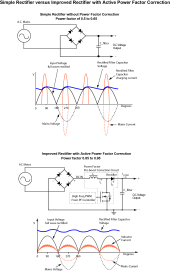
The cheap chargers likely have a simple rectifier-filter capacitor which has a high, short current peak at sinewave voltage peak. Also known as high crest factor and has a poor power factor. This peak current can be 5-8 times the rms equivalent current.

How does your CT-ESP8266 react to such a current profile? You have to sample fast enough and calculate rms equivalent. Also need to be sure the CT transformer is large enough not to approach saturation at the high current peaks.

The long extension cord likely adds enough series resistance to lengthen the chargers' power supply filter capacitor charging period, reducing peak current to a more reasonable current profile the ESP8266 can represent better. This also increases the ripple voltage on the charger's AC to DC filter capacitor and if the valley of the ripple dips below a minimum required level by the regulator in the charger it can show up on the output of charger.

Any power supply or charger above 500 watts really needs power factor correction circuitry. Many newer computer power supplies have power factor correction circuitry, driven by EU regulations on appliance minimum power factor requirements.

If you feed such a poor power factor, high peak current, charger from a generator, the generator wattage rating needs to be 3-5 times the wattage rating of charger.

Full Wave rectified Power Factor diagram.png
 
Last edited:
To close the thread:-

I tried adjusting the cabling from the CT which didn't help so decided to adjust the software code instead!
The overall current measured was averaged over 400mS - changing this to average the current measured over 1000mS has resolved the issue. :)
 
Back
Top