diy solar

diy solar

What REALLY requires a pure sine inverter?

What do you mean by "There is nothing like a PFC "? The active PFC also boost the DC output Voltage. That topology used in many power supplies these day, I.E. TV and PC power supplies.
But then again, are you still getting PFC of close to 1 or not since you made the test?
Here is the example of the PFC topology:
EXACTLY!
This application note is showing all the stuff required to compensate the drawbacks of a sine input to a DC rectifier and try to offset the current pulses on high power DC applications.
 
EXACTLY!
This application note is showing all the stuff required to compensate the drawbacks of a sine input to a DC rectifier and try to offset the current pulses on high power DC applications.
But you see, when you use modified sine wave, you have dead gap which affect the function of the PFC.
You still do not tell me of the PFC i still close to 1 or not based on your test, that will prove if the Modified sine wave causes the issue with PFC or not.
Learn more here and look at the wave form of your PFC power supply:
 
Motors (except brushed universal motors) will run 20% hotter on mod-sine
Some fancy power tool chargers require PSW, others don't. Trial and error ! and cash

The other thing is PSW can be grounded conventionality, MSW cannot be grounded, each leg of the 120V is floating at 66VAC and you can have a big shock hazzard at the battery terminals.
 
@rin67630
Sorry man - you go right ahead using msw inverters. Despite the well-knowns such as highly inductive loads running hot, this academic argument doesn't play out in the real world for stuff you care about. Especially given that the component quality, QC and manufacturing of many of our devices are less than stellar.

How? Part of a user's toolkit should be a handheld IR pointing thermometer, preferably with a little laser for pointing accuracy. For those less-than obvious touch-feely temperature tests, the IR themometer reveals that pure-sine wave powered products runs cooler. Point it at power supply components, exhaust outlets and so forth.

Ie, it's easy to duplicate this test at home.

There is a real answer for saving money though - LED lighting. With \modern\ led lighting, including household led bulbs run off an inverter, you can save money there by not making it part of your main PSW inverter outlet. A much less expensive separate MSW inverter can drive these led lights without flickering much cheaper. That's the ONLY use I have for msw inverters these days. Unfortunately, they too don't last as long, perhaps 1 year max on msw, so there's that. Hmm.. when viewed long term, I should probably dump it.
 
But you see, when you use modified sine wave, you have dead gap which affect the function of the PFC.
You still do not tell me of the PFC i still close to 1 or not based on your test, that will prove if the Modified sine wave causes the issue with PFC or not.
Learn more here and look at the wave form of your PFC power supply:
OK we had a different comprehension of the term PFC you were not speaking about cosinus phi.

In fact a modified sine has a far better PFC than a regular sine on a rectifier-capacitor input.
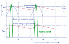
On most power supplies (not the very hightech stuff described by Infineon) the power transmission occurs only for very short time during the crest, when the peak input voltage exceeds the remaining capacitor voltage.
The modified sine will supply their peak voltage for a longer time, being ways more efficient.

We have also a somewhat different picture in Europe with 240V AC.
Most power supplies are of universal design 110V-240V AC.
They will rectify a 110V sine to ~130V DC.
With a modified sine they will get a bit less, since the square peak voltage is lower for the same energy so the DC-DC converter could get a bit under-voltaged. That does not happen with 220V AC inverters.


Motors (except brushed universal motors) will run 20% hotter on mod-sine
Absolutely. That is a very valid point for asyncronous motors.

The other thing is PSW can be grounded conventionality, MSW cannot be grounded, each leg of the 120V is floating at 66VAC and you can have a big shock hazzard at the battery terminals.
That depends heavily on the inverter design. Of course, non isolated inverters with just booster coils inside are an absolute no-go.
 
There is a real answer for saving money though - LED lighting. With \modern\ led lighting, including household led bulbs run off an inverter, you can save money there by not making it part of your main PSW inverter outlet. A much less expensive separate MSW inverter can drive these led lights without flickering much cheaper. That's the ONLY use I have for msw inverters these days. Unfortunately, they too don't last as long, perhaps 1 year max on msw, so there's that. Hmm.. when viewed long term, I should probably dump it.
If you make a separate circuit anyway for LED lighting, you should run them with DC-DC converters. Completely forget AC.
 
I guess the $64 question is if mod-sine-wave is the way to go, then why aren't the power companies saving money by pushing msw into our outlets? <running and ducking> :)
 
QC and manufacturing of many of our devices are less than stellar.
unfortunaltely a valid point, but also for pure sine Chinese models as well.
How? Part of a user's toolkit should be a handheld IR pointing thermometer, preferably with a little laser for pointing accuracy. For those less-than obvious touch-feely temperature tests, the IR themometer reveals that pure-sine wave powered products runs cooler.
Not my computer / screen power supply anyway. It just runs identically well.
 
"In fact a modified sine has a far better PFC than a regular sine on a rectifier-capacitor input." Can you provide the link?
 
I guess the $64 question is if mod-sine-wave is the way to go, then why aren't the power companies saving money by pushing msw into our outlets? <running and ducking> :)
I never pretended MSW were universal. Power companies run tri-phase and still operate high power transformers. Anything inductive or AC-capacitive will NOT run well on MSW.
 
"In fact a modified sine has a far better PFC than a regular sine on a rectifier-capacitor input." Can you provide the link?
1620803312087.png
This is a didactic picture, with less ripple (0.5% typical), you get even shorter and much higher current pulses.
In fact just at the opposite of what @MurphyGuy said:
its not the modified sine inverters that are very hard on electronics, but the electronics that are very hard on true sine inverters.

With a MSW input, the conduction phase is as long as the pulse sustains. the power transmission is ways better.
 
Last edited:
Now show the modified sine wave version of the graph.
BTW, 110VAC will charge the cap to about 155VDC when rectified (Vrms X 1.414), not 130VDC.
Most SMPS in the US now are rated at 100 ~ 240VAC,
 
Last edited:
Now show the modified sine wave version of the graph.
BTW, 110VAC will charge the cap to about 155VDC when rectified (Vp X 1.414), not 130VDC.
Most SMPS power supplies in the US now are rated at 100 ~ 240VAC,
Yes, the 130 V guess was somewhat low.
In fact there is not much literature available about rectifying modified sine.
One should get a short intensive current peak followed by a plateau as long as the half cycle persists....
 
Do you just BELIEVE that or have you got a concrete experience?
Everything that internally directly rectify AC to DC before converting to required voltages (almost everything today) runs well (better) with modified sine.
Old stuff with traditional transformers not that well.
I'm an electrical engineer, and while power inverters are not within my experience and specialty, I have done extensive research into battery based inverter systems.

I've also had the privilege of chatting with the engineers at SMA America.

I don't have beliefs, specifically the irrational type.. I try to avoid such emotional disabilities like I avoid Ebola.

Transformers are not the problem, in fact, if anything, the inductance in a transformer is more likely to smooth out a modified wave than anything else.
It is the rectification circuits, voltage control, etc. that are the problem. When your television stops working, it won't matter to you if the video signal processor blew or the power supply blew.. only thing you'll care about is that it doesn't work.

A $3000 high tech OLED 70 inch television COULD be made to accept a modified wave, they just aren't because the dirtier the power input, the more processing is needed to clean it up, and the higher the quality of your power supply, the more it costs.

That's what its all about.. just money. The power inputs of most things are designed to run on a clean sine wave.

By the way, it is the older stuff that does better with modified sine. Older stuff is built with larger and more robust components, and while they don't meet today's standards for microchips, they didn't need to back then.

I would bet that a microwave from the 1980's would probably do fine with a modified sine inverter..
 
My first inverter was a Harbor Freight modified square wave unit. It lasted for about a day, it didn't quit, we just couldn't stand the loud droning from our Hunter ceiling fan.
Replaced it with a supposedly pure sine wave unit by WZRELB, AKA Reliable. It made the droning noise bearable, but it was still there.
My present system uses the 3Kw MPP all in one unit, and the Hunter fan is absolutely silent.
First hand experience says always use a quality pure sine wave inverter.

 
I'm an electrical engineer, and while power inverters are not within my experience and specialty, I have done extensive research into battery based inverter systems
Thanks for your perspective. I reached the same conclusion about the wasted effort trying to make a MSW work. It is stronger than a belief but just my opinion on where I want to focus my energy. That is why my initial response was to focus on Sine wave or go DC. Of course I assumed 12 VDC. As the OP said, LEDs run on DC. Others are free to walk about.
 
Last edited:
There is a real answer for saving money though - LED lighting. With \modern\ led lighting, including household led bulbs run off an inverter, you can save money there by not making it part of your main PSW inverter outlet. A much less expensive separate MSW inverter can drive these led lights without flickering much cheaper.

I have several LEDs that will not work at all on MSW.
 
Back
Top