diy solar

diy solar

What's going on here? JBD BMS reading on app

ssanvero

New Member
Joined
Feb 18, 2021
Messages
22
Hi guys,

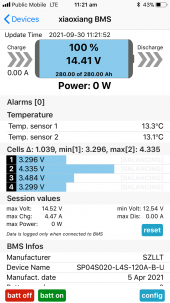
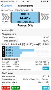
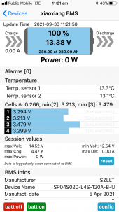
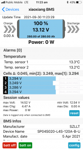
I've just connected my battery to my Renogy B2B Mppt charger and I'm getting these readings below, when I turn the engine on.

I've applied the caps on max and min volts, so not sure why I'm getting these spikes still. Any idea why this could be happening?

Also the voltage of the batteries goes from 14.4V to 13.12V yet it still reads 100%, which I think the battery should be at 100% (I've only charged it) but the voltage doesn't seem right.

Appreciate any thoughts!
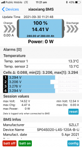
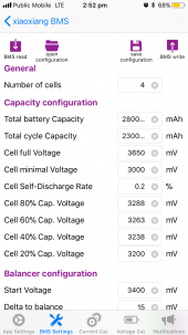
IMG_0585.PNGIMG_0586.PNGIMG_0587.PNGIMG_0588.PNGIMG_0589.PNG
 
Please post pics of the settings. The BMS will only report more accurate SOC levels after a few cycles.
Did you top balance / equalise the cells before use ?
You also need to check / calibrate the current on the BMS. Also confirm the cell voltage calibration on the BMS with a DMM. Normally this is correct from the factory.
Hopefully you are not getting engine electrical noise upsetting the BMS.
 
Last edited:
Hi Pierre,

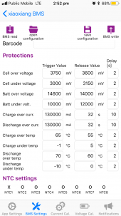
Here are the settings they're currently on.

IMG_0600.PNGIMG_0601.PNG


I didn't top balance them but when I had initially set them up the cells were very close to balanced.

Okay, I'll do some research and try test cell voltage calibration.

Thanks!
 
4.34v is dangerous territory.

If the overvoltage is set to 3.75v you should have had a BMS overvoltage shutdown.

You should shut it down now to prevent cell damage. Measure individual cells with a DVM.

Beside just a bad bms I would suspect poor battery connections or P- , B- BMS leads reversed.
 
So measuring the individual cells... they all measure 3.29V.

There's something definitely wrong, even when I'm discharging through the inverter and just have my laptop plugged in, the voltages read in the 2.8s and I get the low voltage warning and at least the BMS shuts down the batteries. But very confused what is going wrong. Open to any suggestions on how to start investigating?
 
I would start realtime comparision cell by cell what you read on DVM and corresponding read from BMS report. It might be the bms has lost all its calibrations.

3.29v rested a minute with no load is close to 50% state of charge. Check voltage across bus bars from cell terminal to cell terminal at some load to see if their is excessive voltage drop across connections. Make sure you consistantly have BMS sense wires connected on negative side cell terminals. Each sense line from BMS is common to two adjacent cells. You don't want some have two bus bars with cell and others having no bus bars for cell sense between sense lines to BMS. If you feel more heat on some connections that is sign of bad connection.
 
Possibly some connection issues with the voltage sense wires. Need to verify voltage at the connector.
 
Hi Pierre,

Here are the settings they're currently on.

View attachment 67336View attachment 67337


I didn't top balance them but when I had initially set them up the cells were very close to balanced.

Okay, I'll do some research and try test cell voltage calibration.

Thanks!
The settings seem fine for now - some fine tuning can take place later. I suspect something external to the BMS e.g. poor wire contact / connection. As mentioned above , it is critical that the voltage sense harness functions perfectly. It is very easy to not properly crimp the terminals onto those thin wires - sometimes onto the pvc outer instead of the bare wire.
 
I would start realtime comparision cell by cell what you read on DVM and corresponding read from BMS report. It might be the bms has lost all its calibrations.

3.29v rested a minute with no load is close to 50% state of charge. Check voltage across bus bars from cell terminal to cell terminal at some load to see if their is excessive voltage drop across connections. Make sure you consistantly have BMS sense wires connected on negative side cell terminals. Each sense line from BMS is common to two adjacent cells. You don't want some have two bus bars with cell and others having no bus bars for cell sense between sense lines to BMS. If you feel more heat on some connections that is sign of bad connection.
Hi RCinFLA,

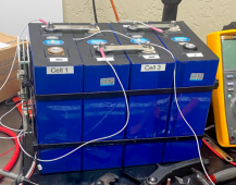
Okay I'm very new to all this so when you say check voltages across bus bars from cell terminal to cell terminal what does that exactly mean? If we use this pack as an example (not mine), are you saying check cell 1's positive terminal to cell 2's negative terminal? and repeat that for the other one?
1633405321463.png

I'm pretty sure I've connected all the sense wires (assume these are the balance cables?) correctly but you say connected to the negative side cell terminals, shouldn't they be on the positive of each of the cells except for the main negative?

Not sure what you mean here? "You don't want some have two bus bars with cell and others having no bus bars for cell sense between sense lines to BMS."

Appreciate the help!
Hans
 
Possibly some connection issues with the voltage sense wires. Need to verify voltage at the connector.
When you say at the connector you mean the connector point where the balance cables connect to the actual BMS?
 
When you say at the connector you mean the connector point where the balance cables connect to the actual BMS?
Yes, remove the cable from the BMS and check voltages on the connector. Also need to connect the battery negative to the B- terminal on the BMS.
 
Thank you guys! it was the balancing cables connection points a couple of the nuts were really loose. At least that was an easy fix!
 
Back
Top