Andy6ft4Tall
New Member
- Joined
- Jul 21, 2021
- Messages
- 33
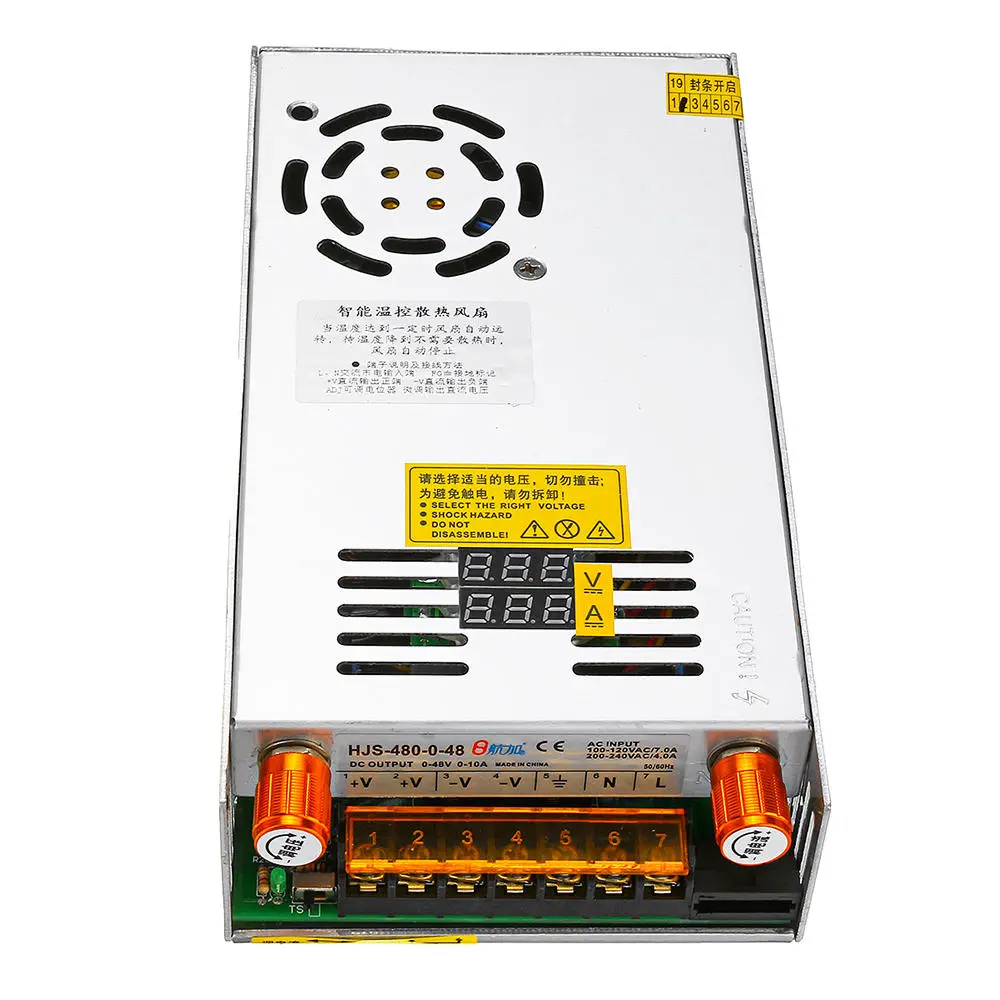
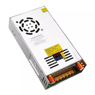
After noticing this adjustable power supply on Aliepress, that is clearly made from a PC power supply and an adjustable DC regulator.
I was wondering if anyone any idea which regulators would i need to buy?
I already have a PC power supply with an output of 65 amps at 12v.
So i just need to regulate the output of the volts and amps and a digital display.
 www.aliexpress.com
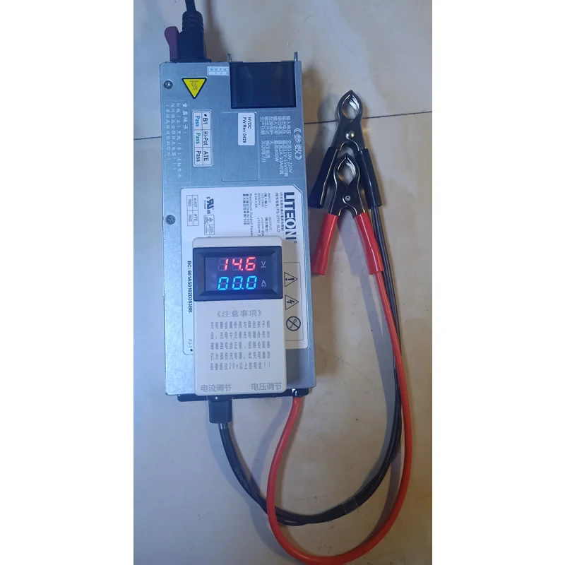
I would be using this as a bench top power supply to bulk charge 12v (4 cells) Lifepo4 packs
I was wondering if anyone any idea which regulators would i need to buy?
I already have a PC power supply with an output of 65 amps at 12v.
So i just need to regulate the output of the volts and amps and a digital display.
50.89US $ |Refit Lithium Iron Phosphate Charger Polymer Battery 12.6v14.6v50a Voltage And Current Display 4 Strings - Integrated Circuits - AliExpress
Smarter Shopping, Better Living! Aliexpress.com
I would be using this as a bench top power supply to bulk charge 12v (4 cells) Lifepo4 packs