What's the best way to splice AC in an RV?

chaostactics

New Member
Joined
Jan 28, 2023
Messages
32
Location
Maryland
I need to connect my Victron inverter/charger to shore power. The inverter charger is all the way at the front of the trailer and the shore power outlet is on the back of the RV. So the shore power is now run to the converter/main panel in the RV but I will disconnect that, and splice the shore power wire to the wire running to the inverter charger. Most resources online about best practices in an RV discuss the splicing of DC power only. The main panel/converter is mid-way down the RV. RV is 26'
 
Splice is the easy part:
The utility cord will connect to a J-Box just inside the inlet. From the J-box to the breaker panel is NMB (romex). Remove the breaker panel and remove the main feeder. Add a j-box and connect same to extend to the front. Connect a new wire to the main panel same place the utility feed was removed and connect this wire to the inverter output.

Hard part is pulling that wire from the breaker panel to the front area through blind compartments, under the floor or through the wall. And if this part is easy, the job is a slam dunk.
 
Remove the breaker panel and remove the main feeder. Add a j-box and connect same to extend to the front. Connect a new wire to the main panel same place the utility feed was removed and connect this wire to the inverter output.
I was assuming the old converter was being completely removed.

But that brings up the question about whether DC needs to be brought up to the existing DC distribution panel (where the old converter is located?).
 
I've started using Wago 221 Lever-Nuts in my (small) RV - they work with both stranded and solid wire, both AC and DC, and tend to be more compact than wire nuts. I've also read that wire nuts are not supposed to be used in a vehicle (due to vibration loosening them) but I'm not sure how big a problem that is.

Downside: not cheap.
Upside: easy to do temporary disconnections (which seems to be something that happens more frequently in a RV)
 
I was assuming the old converter was being completely removed.

But that brings up the question about whether DC needs to be brought up to the existing DC distribution panel (where the old converter is located?).
Yes the converter should be removed or disabled from the AC-DC distribution panel.

I am assuming the the battery is already up front and has a DC connection to the existing fuse/distribution panel. I am further assuming the Victron is going in the front because that is where the existing battery is located.
 
I was assuming the old converter was being completely removed.

But that brings up the question about whether DC needs to be brought up to the existing DC distribution panel (where the old converter is located?).
i'm leaving the converter where it is. Just unhook it.
 
Yes the converter should be removed or disabled from the AC-DC distribution panel.

I am assuming the the battery is already up front and has a DC connection to the existing fuse/distribution panel. I am further assuming the Victron is going in the front because that is where the existing battery is located.

That's correct, mostly correct the 12v will route from the battery via the Victron inverter charger to the Lyxn bus, i'm unhooking the current tongue-mouted house battery. I'm also not reusing that wiring.

The new battery is a 300 mAh LifePO in the storage compartment under the bed. The inverter charger, lynx bus, MPPT, and various dongles will all be located back to back to the battery on the other side of the bulkhead between the pass-through storage and under the bed. So 6/3 or 6/2 (see my other thread) is going to go from the Victron to the current panel, 10/3 or 10/2 from the shore power feeder that supplies the panel now to the Victron, 6 AWG from the Victron to the 12v system panel, and 2/0 cable from the Victron to the battery.

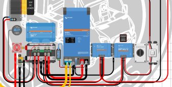
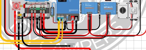
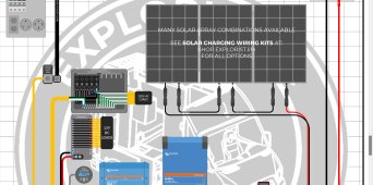
Im using the following set up with 600w solar, 100|50 mppt, and no alternator / DC|DC circuitupper wiring scheme.jpgLower wire scheme.jpg since its a trailer.
 

Attachments

  • top of solar diagram.jpg
    top of solar diagram.jpg
    414.2 KB · Views: 21
Last edited:
I need to connect my Victron inverter/charger to shore power . . . the shore power is now run to the converter/main panel in the RV but I will disconnect that, and splice the shore power wire to the wire running to the inverter charger.

I think you're doing what I did with my Victron Multiplus II (My System Diagram)

If that's the case, then I think you're running shore power directly from your transfer switch to your Victron. Then you're running your Victron's AC out into your AC breaker panel. Is this all correct?

If so, like you I think, I had to connect disconnect my transfer switch output from the AC breaker panel and run it to my Victron. To do this, I needed to splice my 6/3 transfer switch output to a 6/3 AC cord connected to my Victron.

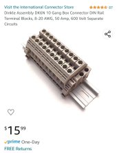
To connect the two AC lines, I used a Marathon terminal block which I mounted inside a plastic electrical box.
 
12 volts nominal over 52 feet round trip requires 1 guage wire to keep the voltage drop below 3%
I doubt the mechanical lugs on the dc distribution center will even accept 1 awg.
 
You're adding a good amount of extra length to the AC circuit. That means that you may have to reconsider the gauge of the cable that is being used. I would at least consider relocating where the shore power comes into the RV. That would allow for a much shorter run to the inverter.
 
You're adding a good amount of extra length to the AC circuit. That means that you may have to reconsider the gauge of the cable that is being used. I would at least consider relocating where the shore power comes into the RV. That would allow for a much shorter run to the inverter.
I'm going to be running 10/3, the drop on a 30 Amp supply should be near negligible.
 
alternating current
Do you mean that there is no Voltage drops on the wires when the load is drawing current from the AC power source?
So if I hook up a resistor to the the AC power using two wires, which basically we have 3 resistors in series since the two wires are just a very low Ohm resistors, that means I should not even have Vdrops on the resistor or on the wires because we are dealing with AC current?
 
Last edited:
Back
Top