diy solar

diy solar

Why not to use Daly BMS with MPPT controllers

I'm partial about using DC/DC converters in this kind of application, mainly because they're not made to be power cycled all the time. But here that's not really a problem since it should pretty much never cycle, what's more of a problem is that it adds a point of failure.

I wish there was a simple 3 pins IC in something like a TO-220 package who would be basically a mosfet with a fixed 50 % duty cycle oscillator to control it. That would make a divide by 2 voltage converter without the complexity of a DC/DC converter and would be plenty enough for lots of applications like this even if it's not regulated, etc...

We can imagine some different ones in smaller and bigger packages for lower/higher power stuff, and with a few other duty cycles available like 20, 25, 33, 67, 75, 80 %... that would be so cool.

I don't think a fixed duty cycle will work great, it's not as simple as 50% duty cycle will give you half the voltage. You need to have feedback voltage loop to maintain the correct voltage because the load dictates the voltage

I guess if you know the load very well you can size the inductor/capacitor correctly, and experiment with the duty cycle to get it right. But the buck converter will be tuned only for the given load. Change the load, and if it's too small you might get full input voltage, on the output.
 
Well, without filtering 50 % duty cycle will give you half the voltage on average but you're right, as soon as you add some filtering there wil be a problem (and you must add some filtering unless you're powering a heater basically). Hmm, that's unfortunate.
 
A step-down converter will easily whitstand millions of power-cycles - or at least much more cycles than a high power relay will whitstand.
 
PWM, without a diode and filtered, produces a voltage based on duty ratio. I mean PWM that pull up to source and pulls back down to ground, selecting between those two voltages, with a switch that conducts in both directions.

PWM switch-mode converter, through an inductor and with a free-wheeling diode into a capacitor, is a buck converter. Voltage out is based on duty ratio only for some loads; too light a load and voltage would rise to the source.

As Brad says, feedback is required (only for the case of too light a load).

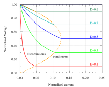
In a Buck PWM converter, it can operate with current through inductor ramping up and down in sawtooth pattern, when voltage source is connected through FET switch to inductor and load, current in inductor rises. When FET switches off, current continues to flow through inductor to load but circuit is completed through diode to ground and current ramps down. Current never drops to zero. Large enough inductor smooths current, but is slow to respond to changes in load and output voltage dips if load increases. "Continuous conduction mode" (figure 4)

Too small a load (or inductance too low) and voltage would continue to rise above what duty ratio indicates. "Discontinuous conduction mode" (figure 5), current in inductor drops to zero while FET switch is off. Regulation by feedback involves either smaller duty ratio or skipping pulses of PWM.

Figure 6 shows output voltage depending on duty ratio and load:
1654609338655.png


The math gets pretty hairy. College level stuff.
Then there are switching losses, EMI, etc.
Designed correctly, SMPS are efficient and reliable. Not all are, and like everything we design into our systems, its characteristics have to be considered.
 
I hate to be the ignorant one in the room but truth be known, I am struggling to hold on to the conversation here. Is there any consensus in terms of what might be the best approach? The @BradCagle solution seems efficient, effective, and doable for a noob like myself but I get lost searching for the downside. Can someone smarter than me please summarize?
 
I hate to be the ignorant one in the room but truth be known, I am struggling to hold on to the conversation here. Is there any consensus in terms of what might be the best approach? The @BradCagle solution seems efficient, effective, and doable for a noob like myself but I get lost searching for the downside. Can someone smarter than me please summarize?

I think the solution in my video will work for most. If your system is higher than 48v you'll need to place a buck convertor (device that lowers the 48v to 12v so the contactor is happy) between the control board, and the contactor. I linked a suitable buck convertor in the description of the video. I might do a short follow up video that shows that part.

You can pretty much ignore our technical conversation after (unless you're interested), it's really just us talking about how to make it more simple.
Thank you, @BradCagle . That is what I had taken away from the video. I really appreciate the effort that went into making it. I also appreciate all the thought that went into this entire forum thread. It was very helpful. Thank you Brad for the solution and everyone for their contribution.
 
The contactor specs show this as a normally open contactor with relay coil resistance of 3.14 ohms. If the battery voltage is 13.8v for example, wouldn't this be drawing about 4.4 amps continuously to keep the contactor closed during normal battery charging/usage?
 
The important bit is the schmitt trigger, the buck converter is just a power supply and could easily be replaced by a zener/resitor arrangement, the actual power consumption is minimal (a few mA when the relay is on).

@Davismltc did a version for a 12V pack with a zener supply.
I did find DC-DC buck converters on eBay @ 2 for ~ $1.00 and plan to build the initial circuit with one of those, rather than a zener supply. I don't intend to have battery supply voltage drop below 12v, but will test it down to 10v.
Input 3.2v~40v
Output 1.25~30v
Current 3A (max)
 
Last edited:
The contactor specs show this as a normally open contactor with relay coil resistance of 3.14 ohms. If the battery voltage is 13.8v for example, wouldn't this be drawing about 4.4 amps continuously to keep the contactor closed during normal battery charging/usage?

No. This particular contactor has Tyco's "Economizer" that lowers the holding current after it closes. It's I assume a chopper circuit like you would see on stepper motor controllers.

I've measured it, and it only requires 1.7w to hold.

■ Built-in coil economizer – only 1.7W hold power @ 12VDC and it limits back EMF to 0V. Models requiring extenal economizer also available
 
That's awesome! I only saw the specs on battery hookup.

What's the power draw for the combined units together (e.g. the controller relay and contactor together)?
 
The contactor specs show this as a normally open contactor with relay coil resistance of 3.14 ohms. If the battery voltage is 13.8v for example, wouldn't this be drawing about 4.4 amps continuously to keep the contactor closed during normal battery charging/usage?

No. This particular contactor has Tyco's "Economizer" that lowers the holding current after it closes. It's I assume a chopper circuit like you would see on stepper motor controllers.

I've measured it, and it only requires 1.7w to hold.

That's one possibility. Then you get all the reliability of a semiconductor driver, for a device as simple as a coil of wire and Gauss's law for magnetism. Sometimes, silicon is the most reliable part of a product, and sometimes it is the first to go.

A PTC thermistor could also serve as an economizer, but would dissipate much more energy in its resistance than is needed for IR drop of the coil to generate sufficient magnetic field.

Can you measure AC signal coming from your economizer as it switches?

I prefer the economizer in a contactor resold by SMA (made by ABB, if I recall correctly.)
It has two windings on the core. One has 10 ohms DC resistance, which would draw 5A, 250W from 50V battery if left connected. That slams the contacts closed hard. A small NC auxiliary contact shorts out a high resistance winding in series with the 10 ohm winding. As soon as relay coil has pulled in the core and closed contacts, this inserts a high resistance, high turn count winding in series. The 50V battery voltage is dropped across the long, thin wire of second winding, producing enough field strength to hold relay closed.

Here's a similar scheme, dual parallel coils from Gigavac. Uses electronic timer rather than separate electromechanical contact.

 
You can also have a capacitor in // with a resistor and the whole thing in series with the relay coil. The capacitor allow a burst of high current at first and then it become open circuit so the current gets limited by the resistor. It's not the most efficient solution but it avoids semiconductors and should last at least as long as the rest of the relay.
 
You can also have a capacitor in // with a resistor and the whole thing in series with the relay coil. The capacitor allow a burst of high current at first and then it become open circuit so the current gets limited by the resistor. It's not the most efficient solution but it avoids semiconductors and should last at least as long as the rest of the relay.

Interesting. The cap will pass current until its fully charged, then it blocks the dc. But won't the resistor just burn up/waste the current it's limiting to the contactor?
 
Yep, exactly. You need to take into account the power dissipated in the resistor.

It start to get a problem with bigger relays as the coil will have a higher power consumption.

But just for an example for a relay coil rated 24 V and 50 Ohms, the nominal current would be 0.48 A. Let's say we can reduce the current to 1/3 of the nominal once the relay toggled (1/3 to 1/2 is a safe bet for any relay usually) so 0.16 A. At 24 V that would be a 150 Ohms load so the resistor would need to be 100 Ohms. Then the power dissipated in the resistor would be 2.6 W so a 5 W resistor would be ok, a 10 W one or more would be better.

The Kilovac must be specifically designed to be able to drop the current to a very low value compared to the initial current (3 Ohms that's 8 A @ 24 V and it drops to 0.07 A with the built-in economizer). Actually it would burn after a few seconds without the economizer because it would (try to) dissipate almost 200 W... ?
 
Back
Top