diy solar

diy solar

Why not to use Daly BMS with MPPT controllers

One concern I have with the above "Fail Safe" circuit is that once it energizes the relays, it puts a brief load on the battery which brings the battery voltage back in line, and the relay reconnects the PV panel. It will continue to cycle like this, keeping the battery from overcharging, but I think the cycling of the relay(s) and PV panels may be too frequent.

What I think might be better is to have the "Fail Safe" short out the PV panel and simultaneously trigger a visual and audible alarm for any over voltage condition. Once the fail safe is triggered it should remain triggered, with all PV panel charging halted and the alarm continuing to sound until manually reset with a switch. Keep in mind that the only reason the Fail Safe has tripped is if some other piece of equipment has already failed. I think it's probably better to trigger an alarm and have the charging halted, so the system gets checked out for the fault, rather than cycle the relays and PV panels excessively.

Each relay now only draws about 20 milliamps (due to a change in the circuit design), and the LED and piezo buzzer add just a few more milliamps. With a fully charged battery, the alarm could sound for days, if necessary, depending on other battery loads.

A second concern I had was regarding contact arcing that may occur when the relay shorts out the PV panel. I've been working on the circuit design and think I can short out the PV panel with an SCR instead of with relay contacts. This should eliminate any concern to the solar charge controller inputs caused by contact arcing. It also lowers the fails safe's current draw to less the a tenth of an amp while sounding the alarms and interrupting the PV panel charging. Monitoring alone will be just a couple of milliamps. Kind of a win, win, if it tests out okay.

Since the vast majority of the time the Fail Safe is only monitoring, I thought I'd also include a "Test" button. Just a momentary switch to trigger an overvoltage simulation to the comparator and trigger the alarm. Kind of a like how a smoke detector is tested, only the Fail Safe would require a manual reset to stop its alarm.
 
Last edited:
It seems as though I've hijacked the OP's thread with a fail safe design discussion. I apologize and will stop further comments about it.
 
Back in the beginning of this thread I suggested an explosive fuse. Well, apparantly they do exist. They are used in e.g. Tesla cars. They are called pyro fuses.
You can obtain them from used car part sellers. Most of the ebay sellers are selling them for ludicrous amounts of cash - local stores are perhaps your best bet.
I hope someone will try them out and report here with info. E.g. which voltage/current will trip the pyrotechnical fuse. We do need to figure out a proper driver circuit. With plenty of fail safe systems inside. E.g mitigate an esd lightning strike a few km away. You do not want it to blow by any external factor. There are also patents from Tesla to read.
Rube Goldberg is alive and well in this discussion.
Circuit breakers exist that can be remotely tripped, not particularly expensive. All you need is something to monitor the voltage and trip the breaker when the voltage is too high. You can also have it text or email you when that happens, or just use the text or email to let you walk over and open the breaker. Use a Raspberry Pi if necessary.
 
Back in the beginning of this thread I suggested an explosive fuse. Well, apparantly they do exist. They are used in e.g. Tesla cars. They are called pyro fuses.
You can obtain them from used car part sellers. Most of the ebay sellers are selling them for ludicrous amounts of cash - local stores are perhaps your best bet.
I hope someone will try them out and report here with info. E.g. which voltage/current will trip the pyrotechnical fuse. We do need to figure out a proper driver circuit. With plenty of fail safe systems inside. E.g mitigate an esd lightning strike a few km away. You do not want it to blow by any external factor. There are also patents from Tesla to read.
gigavac sells them too with specification sheet :)

edit: used to. just checked and don’t see them being displayed anymore

i have no plans of integrating a pyro fuse because they are one use hehe

normally used to de energize upon crash
 
i have no plans of integrating a pyro fuse because they are one use hehe

normally used to de energize upon crash

Sounds inconvenient.

Some of our cars have a crash-sensor switch which shuts off fuel pump. Usually located in the trunk under panels somewhere. It is manually resettable.
The pumps are shut off anyway when engine isn't running, but I guess that isn't 100% sure way to stop feeding the fire, so an impact sensor too.

A spring-loaded switch with inertial trip could work for EVs.
I trust less safety circuits which require a signal to activate (shut off), compared to those which require a keep-alive signal.
My gas furnace has several temperature sensors to activate blower fan. Either over-temperature or broken wire activates it. Gotta debug it one of these days - fan keeps cycling even with thermostat set to "off".
 
Interesting discussion. Great, one more thing to worry about! ?

My take on this, is a simple solution as suggested with a relay disconnecting the PV array from the scc. To trigger the relay a vat-4300 shunt can be used. It’s cheap and have a programmable over voltage protection (OVP) feature that trigger a relay output. It can withstand 300v. I don’t know the release time/voltage of the OVP, but if a 2-pole relay is used you might wire the unused pole to hold itself opened once it has been triggered, and put a manual reset switch to release it.

I have actually thought of a protection circuit like this previously to address a different issue, and that actually makes me think the Daly BMS might survive the abuse. The issue has happened to me when I had a bad top balance and the bms trips the charge protection. When that happens the output voltage of the scc fires up to the current mppt voltage for a Short period of time before it goes down to battery voltage. It is with a esmart3 scc and ~120v array. My inverter doesn’t like this at all and goes into a rail voltage protect mode. My Daly BMS have survived though.

(PS. I managed to break a lot of Daly BMSs in other ways)
 
My take on this, is a simple solution as suggested with a relay disconnecting the PV array from the scc. To trigger the relay a vat-4300 shunt can be used. It’s cheap and have a programmable over voltage protection (OVP) feature that trigger a relay output. It can withstand 300v.
I watched a demo on a Juntek VAT-4300 and the voltage didn't seem very accurate as the current varied (fast forward to 13:37):


Maybe it does better when not measuring current?
 
Nice review you found!

What we see to the left is the display of the dummy load. It will display the voltage drop over itself.

When there’s no load the voltage displays both show the same.

The voltage difference when applying current is most likely the voltage drop over the wire. (Since the difference increases with the current).

Even if this is not the case I think the accuracy should be good enough for this application, what is more important is how fast it reacts on OVP.

Thinking even further, there will not be any current when this happen, it is actually why it happens. (The bms shut off the chgMOS, the current goes to zero-> the rail jumps to mppt voltage). When (and if) the BMS breaks and short the chgMOS and the current flows again, the OVP should have triggered (with a correct voltage reading), preventing this from happening. If it is fast enough…

// X
 
New theory to protect against MPPT FET shorts:


Over Voltage protection is not really possible on battery side.
I think if you put 500V but only 10A solar string to the battery line, the battery will consume it.
So the line voltage will be only the battery charging voltage.
Like if you put your lab bench power supply to 32V 10A and connect it to parallel 3,2V cells (doing top balance).
It goes up to 4,3V 10A. And only on the PS side (a lot of loss in a thin cable)

Only after battery is full will be the line V high (overcharge ... already too late).

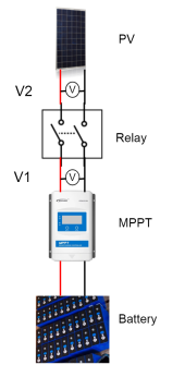
The theoretical solution is to use a relay on PV side (like for a 4-500Voc and 15A PV string) and two voltage meter (before and after relay)
The voltage value is checked periodically (every 10 sec or 1 min or ....).
Relay is controlled with a RasPi for example (that gets the V measurements too)
  • If relay is open (PV not connected to MPPT)
    • If relay-MPPT cable V1 >30V relay remains open: ALERT. Already shorted MPPT, battery V on MPPT PV side.
    • Else If relay-MPPT cable V1 < 30V and relay-PV string cable V2 > 100V (in a 48V system) then relay connects PV to MPPT : all is OK.
  • If relay is closed (PV connected to MPPT)
    • If (both) V measure below 100V then disconnects/opens relay : Possible just shorted MPPT and PV volt is hold down by direct battery connection (or very low light an then also no power will be produced).

The V values are only for example. Needs some calculations with cable resistances.

update: schema

MPPT_FET_error_solution.png
 
Last edited:
concept of relay disconnect between PV and SCC appeals to me. of course fuse too. electronically disconnecting PV just seems really handy.

for a really small LFP system that i worked with, it was worthwhile to disconnect the SCC from the Battery at night.

over a single night, the SCC idle draw was significant enough that adding a bistable relay to fully disconnect from cells at night was worthwhile.

monitoring the PV voltage separately, and noting time since last shutdown, makes reconnecting easy to capture maximum production

this was with a <10Ah battery pack, for context

thanks for the diagram
 
I still like the idea of a simple crowbar, I'm a great advocate of KISS (Keep It Simple Stupid). Few components means few things to go wrong.

Even a 50A thyristor (cheap) is capable of single 10ms surge currents of >600A, should be easily enough to open the 63A DC breakers I have on my 60A MPPTs (they never manage over 50A anyway). The crowbar goes between the MPPT and its breaker so the battery provides the current needed to open the fuse/breaker.

I will admit to being somewhat "over-breakered" with MCBs both at the battery bus bar and at the MPPT.

In reality it doesn't even need to survive, just open the over-current device.
 
It's been a while since I read this thread, but what about a zener on the DC bus set at, say, 3.70V/cell feeding a protection circuit? Even if it then takes +2V to trip, for an 8S pack we're at 3.95V/cell. Bad, but AIUI, not fatal for once-in-a-cell-lifetime failsafe. Doesn't have to be current carrying. If the protection circuit sees voltage on the zener, perhaps sustained for 5s, then it triggers the above mentioned remote trip breaker on all SCCs and sounds the alarm.

If you've already got a Pi running monitoring that should handle it neatly; for fancy you could probably use an Arduino with the power supply idle probably higher than it, but I expect an EE could come up with something that uses discrete components.

If a microcontroller, perhaps Zener -> 100ohm -> Vmon -> VmonProtectZener. We're looking for signal voltage, not protection current sink.
 
As someone here already mentioned, smartest solution is monitor overall battery voltage and just disconnect solar panels if battery go over set voltage.
I you want to go really cheap then why not just 1000V solar DC breaker (~5$) with attached RC servo motor (~3$) to trip the breaker.
Arduino (~3$) to monitor pack voltage and control servo + buzzer.
BMS survives too.
Like this: (not tested yet)
Using widely available parts is the key for cheapest solution.
 
Thinking about this and reading the thread again, I'm thinking about @codfish's idea of the NC relay. However, HVDC NC relays are hard to find and often expensive. More typical battery side relays are still nastily expensive due to amperage and even harder to find in NC, although we probably don't need a full panel voltage rating here, as it should trigger when the voltage is held down by the battery, unlike if it's on panel side, where that seems essential for safety. At that, I'm thinking back to something like the Midnite remote trip breakers on SCC output, a small relay to close a 48V -> 24V converter, and something to trip it. I think some inverters or maybe even BMSs have an alarm output. Perhaps one of these could be commandeered to either trip the breakers directly or drive the relay without another control board.

For another option now, there is the relay based JBD BMS, which uses ~30Wh/day over a MOSFET BMS. However, in this thread, it looks like there is a sense and possibly precharge wire. See post #11 by @Samsonite801 and #19 by @Amitis. Sounds like unless this circuit has HVP, something I suspect it doesn't, aside from maybe letting the magic smoke out being more likely to fail open circuit we're right back where we started with MOSFET BMSs: a creeping high voltage on the DC circuit will end up destroying the batteries if not caught and stopped in time.

Any thoughts? Right now I'm particularly interested if anyone can say anything about the JBD relay BMS, in particular whether it's safe in this situation, or if it's no better than the MOSFET ones, as I'm deciding which BMSs to buy right now.
 
I would go with MOSFET BMSes. MOSFETs are more reliable for long-term usage. And if your concern is that everything may blow away, but you need your batteries as safe as possible - upgrade the MOSFET part of a BMS with better transistors that suit your needs.

If you are so afraid of your charging controller burning out and passing all the voltage to the batteries - check your BMS voltage capabilities and redesign your PV array so the BMS can survive. It would be nice if the highest voltage a BMS can handle was in the specs. This way users will know what to expect. And a lot more people would think about this when they see it in the specs.
 
I imagine 1000V and 500A rated Low Rds mosfet could be insanely exepensive if these things even exist.
 
Thanks, @brum. I'm not in general particularly concerned about the SCC failing, as I've gone for Outback FM-80s, but nevertheless after reading this I'm aware of it as a possibility really up to replacing MOSFETs on the board, and would prefer if my system is safe against this possible, though rather unlikely issue. I think I can reconfigure my system to <100Voc, so it should work with what I already have on hand and plan to get, at some cost in low light performance. Thanks for getting me thinking about that possibility.

Yes, that should really be in the BMS specs for all BMSs out there. Should already be more or less defined, and they just need to tell us what it is. I guess those who have a given BMS can offer MOSFET part numbers, which is probably the limiting factor here.

@Lauri234, Yes. I just checked Digikey. Only one low Rds single MOSFET for a "reasonable" price of ~$25 each - and it doesn't even have a form factor to be suitable. I guess that throws us right back to the primary discussion through this thread of what to do for those who can't arrange panels to be safe in an SCC dead short situation.
 
Cheapest 1000V 63A contactor OV protection device (solar side):
Breaker: https://www.aliexpress.com/item/4001259552119.html?spm=a2g0s.8937460.0.0.1f722e0e9dXpuO
Arduino as programmable voltage sensor: https://www.aliexpress.com/item/100....store_pc_allProduct.8148356.6.55973c84deMWBM
Servo: https://www.aliexpress.com/item/100....store_pc_allProduct.8148356.2.24f21e0e0gdYiq
40v-220VDC (tested) to 5VDC for Arduino (power from battery): https://www.aliexpress.com/item/330....store_pc_allProduct.8148356.2.5568f77aZJKPvV
Concept:
Code: If battery voltage over 58.4V then switch off solar circuit breaker(s).
 
Instead of the 1000V 500A MOSFET for BMS, a lower voltage lower current MOSFET on input of BMS could clamp BMS input (and SCC output) to ground. This would have to be timed to close immediately after BMS disconnects, so it isn't crowbarring battery. It would discharge SCC and inverter capacitors, so a bit of energy from that and power from PV it has to dissipate during falling edge. The clamp has to work before voltage gets too high for BMS, which is why lower voltage MOSFET clamp could work. But it has to be timed fast enough, before voltage on capacitors goes too high. It would be protecting inverter as well.

Some SCC (maybe Midnight Classic?) have such crowbar on their PV input.
Those could provide this protection, if designed to clamp in the event of output over-voltage. But probably designed for input over-voltage only.

Easier, and without timing constraint (in relation to BMS disconnect) would be to clamp PV input to SCC. That would be high voltage, even lower current MOSFET.

But I think remote trip PV breaker is the simple solution. Midnight sells some. One risk is that it isn't failsafe - an open wire would prevent it from functioning. Preferable would be a spring loaded trip for the breakers, with a keep-alive signal holding it closed. RSD similarly uses a keep-alive signal.

The remote trip would function like RC servo Lauri shows, but is simply packaged as another breaker with handles ganged. Rather than being a relay, I think it is just a 1A breaker, which would fast-trip with 5A current. I'd want to wire a resistor in series instead of feeding it battery voltage directly.

Here are some Midnight breakers with remote trip. Looks like built-in, rather than an extra pole ganged.
One is for battery circuit, one for PV (four 150V breakers in series for 600V)


Back
Top