diy solar

diy solar

Will this work for pre-charging inverter capacitors?

An inductor will cause a delay in the current, but not really reduce it. However, the built in resistance of an inductor will cause a bit of an curve in the amp increase and you will be stuck with that resistance on series. You want to make that less, then it will have less affect on the current rise rate.

Actually Inductance would reduce (not delay) the peak inrush. But it would have to be a very large inductor to be able to handle the normal current. (Think about how large your wire into the inverter is and then imagine making a coil out of them. ) Consequently, an inductor is not very practical for this use.
 
Actually Inductance would reduce (not delay) the peak inrush. But it would have to be a very large inductor to be able to handle the normal current. (Think about how large your wire into the inverter is and then imagine making a coil out of them. ) Consequently, an inductor is not very practical for this use.
Reduced inrush by creating an LC with the inverter's caps. I stand corrected.
 
If you want simple, I think you either have to have a parallel "trickle" circuit as @DThames says (either on all the time or on a switch) I've heard that some products use an NTC Thermistor
From Wikipedia:

I looked into thermistors a while back but I did not spend a lot of time on it. The problem I ran into was finding something that was large enough to handle the normal current load an inverter requires.
 
I feel like I am being too negative about everyone's ideas....Sorry.

Unfortunately, having a charge circuit parallel to the connection to the inverter is the only practical solution to the problem that I can think of.

As @krby says, the 3 most obvious signals to automate the path is time, current and voltage. The easiest way to measure current is to measure voltage across a known resistance (V=IR), so it really boils down to time and voltage. I would have to think about this some to come up with a simple, reliable and low-power-draw circuit to do it.

Meanwhile, the best thing I can think of is a momentary push-button that connects the pre-charge resistor to the inverter. (Momentary button so it can't be inadvertently left on when you think the inverter is switched off)

I am a little surprised there arn't existing automated solutions on the market, but I guess switching inverters in and out of a circuit that has a BMS in series is still a little bit on the fringe.
 
One more thing everyone needs to remember: When you *disconnect* the inverter, those internal capacitors remain charged for a while. If the inverter is on, this will drain pretty quickly. If the inverter is off, you might get a nasty surprise if you assume the circuit is not charged.
 
Inter
If I understand the proposal correctly, this would make the problem worse. The problem is caused by the large capacitors across the + and - inside the inverter. However, if you had a large capacitor that was already charged and you switched it in at turn on, it could provide the inrush current in order to protect the BMS. However, you would need to think about how this new capacitor gets charged.... if you aren't careful, you would just move the problem.

View attachment 4277
Interesting discussion. I think the problem is not that the inverter caps are causing in rush current. The problem is their leads are too small to handle the in rush current when the battery is connected. An larger external capacitor with leads that can handle the high current would theoretically take the a large part of the current spike and the downstream capacitors would see less of a spike. (That's my theory anyway!)
 
You're right FIlterguy. Worse. In no way would adding capacitance help anything. The capacitance is the problem.

Perhaps some in-the-box thinking? Why would your BMS be disconnecting the loads frequently? That would not, typically be, an appropriate operating mode.

The solution is easy. The cost is not easy.. You use a contactor, a resistor, and ON-Delay relay. The resistor is put in series with the BMS output and the inverter input. The contactor is put in parallel with the resistor. The ON-Delay relay is put from the BMS output to the system return (or system positive as most BMSes switch the return) to operate itself. When the ON-Delay relay contact closes it energizes the contactor shunting (shorting) the resistor.

Keep in mind that trying the slow startup on many inverters will be bad. As the caps charge and an already switched ON inverter's control circuitry reaches its startup enable voltage the inverter will attempt to start up. Thus instantly draining the capacitors down to below control voltage. This will shut off the inverter as the resistor tries to recharge the caps again. Then around you go. This is called a relaxation oscillator. This would be very bad as the startup process of an inverter is one of the hardest things they have to do. Chaining more than one of these together will toast many of them.

This means the better way is to turn off the inverter before the BMS does. Then when appropriate you turn back on the inverter without ever disconnecting the batteries.

If the inverter is the only load on the batteries then you could instead have the BMS output control the inverter ON/OFF switch. If the inverter is OFF the batteries are not being drained.
 
Inter

Interesting discussion. I think the problem is not that the inverter caps are causing in rush current. The problem is their leads are too small to handle the in rush current when the battery is connected. An larger external capacitor with leads that can handle the high current would theoretically take the a large part of the current spike and the downstream capacitors would see less of a spike. (That's my theory anyway!)

OK.... that raises a rather basic question: What is the problem we are trying to solve?

The problem I have been imagining is the surge current either tripping the BMS over-current-protect or damaging the BMS. The other potential problem is damaging the contacts in the power switch when you turn it on, but if you have a properly rated switch (or contactor), that should not be a problem. I have not even considered damage to the Inverter.

I don't think there is a problem with the capacitor leads being too small. Granted, the leads could not handle the inrush current for a sustained time, but the inrush is so short I doubt there would be a problem.

@Keith C raises a good point about putting the inverter into an oscillating state. I don't know what damage the oscillation will cause, but I am very confident that if it happens, the circuitry was not designed to handle it. Consequently, this argues for a solution that only allows the pre-charge circuit a short time before the main switch is thrown on.

Dang you Keith!!! You just gave me something more to worry about!!! :ROFLMAO:

Perhaps some in-the-box thinking? Why would your BMS be disconnecting the loads frequently? That would not, typically be, an appropriate operating mode.

Since everyone is not even aligned on the problem we are trying to solve, I can't speak for others. However, for me the problem is this: The off grid cabin I am powering is totally shut down when it is not occupied. That means that every time we go there we have to power up the system. Furthermore, it may not be me powering up the system so I need it to be as fool proof as possible. Furthermore, if something goes out I litterly have to get on a plane to go fix it..... so I need the solution to be as durable as possible. Consequently, I want something that is 'flip-a-switch' easy and does not damage any of the equipment.
 
Last edited:
Ah Filter. In your case I can see the desire to disconnect completely. But your situation works fine with a check-list:

Powering up
1) Confirm Inverter Switch is OFF.
2) Turn switch X to position 1 count to five.
3) Turn switch X to position 2.
4) Turn ON inverter.

Powering down before leaving
1) Turn OFF inverter.
2) Turn switch X to OFF.

Yup, a checklist works..... as long as it is followed.
 
Ah Filter. In your case I can see the desire to disconnect completely. But your situation works fine with a check-list:

Powering up
1) Confirm Inverter Switch is OFF.
2) Turn switch X to position 1 count to five.
3) Turn switch X to position 2.
4) Turn ON inverter.

Powering down before leaving
1) Turn OFF inverter.
2) Turn switch X to OFF.

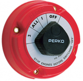
...and my use case (I'm the OP of the this thread) is very similar to this. LiFePO4 bank with an inverter charger stored for weeks at a time, completely disconnected (via a big switch) then connected and put to use. For me, I'm choosing to use a big red 1, 1+2, 2 rotating battery switch. The "2" is the final on position, and I'll have a big label showing which way to turn it so I have to go thru "1" (the pre-charge circuit) on my way to "1+2", then "2".

The problems I'm trying to solve are:
- damaging the inverter
- tripping the BMS
- sparking the switch contacts and damaging them
 
So here is the circuit I was thinking for a manual pre-charge. It is very similar to krby, but I am using a push-button and he is using a rotory switch.

I made the resistor 30ohm, 25 watt because that is what Will specified, but I would be tempted to go with 20ohm 50 watt or even 10 ohm, 100 watt.

EDIT: Corrected schematic
1577985046053.png
Pick your failure mode:
  • krby's rotory switch makes it harder for someone to turn on without pre-charge. (Unfortunately, the rotory switches on the boats can be rotated in both directions. That means that someone could go directly from off to full on without pre-charging)
  • The button makes it harder for someone to leave the pre-charge on and think the system is off.
I keep going back-n-forth on which is the lesser evil.


I am still thinking about how I would automate the pre-charge and turn on.
 
Last edited:
The problems I'm trying to solve are:
- damaging the inverter
- tripping the BMS
- sparking the switch contacts and damaging them

How will the surge hurt the inverter? (I am not saying it can't... I just don't know what the damage mode would be)
 
If I use the bms to trigger the remote of the 220AH victron battery disconnect , and power a 3000w 12v inverter from a 6p4s lithium do I still need a pre-charge? It's not going through BMS
 
I assume you are talking about a circuit like Will shows in several of his videos where he uses the 'load' wire from the BMS to activate a battery disconnect. (Or a big solenoid).

The 'dangerous' point is when the Victron battery protect first turns on. At this point there will be a large but short surge while the capacitors in your inverter charge. I don't know what the current will be but it will briefly spike quite high and then immediately start tapering off. The current will be back down to near steady state in well under a second.

You will have 4 items in the path of that current.

1) Inverter. A 12V 3000W inverter is in the area where the surge current will be quite high, but like I said in my last post, I am not sure how the surge would hurt the inverter. All that energy is going directly into the capacitors.

2) Battery. A big current spike is not good for the battery, but the spike is so short it probably does not matter. (There won't be time for the battery to heat up much and heat is what causes the problems.)

Note: I don't think there is anything to worry about with the battery but, it will be almost impossible for the average Joe to know if there is a problem. If there is damage to the battery, it will almost certainly be something that is not immediately detectable. Furthermore, if there is a problem it is probably a cumulative effect. Consequently, if it does not happen very often, you will never notice it.

3) Victron Battery protect
1577930304770.png

Like I said, I don't know what the peak current is so I don't know if it would exceed the 600A Peak spec of the victron. However, the surge will have tapered down in significantly less than a second. Furthermore, Victron equipment is usually built quite well. If there were a problem with inverter loads, my guess is Victron would either design to deal with it or put something in the manual to warn about it.

When the Victron is signaled to disconnect, it is an entirely different (Easier) situation. At that point, we are 'only' talking about turning off the steady state load. Since the Victron was designed as a disconnect device to protect the battery, I am confident it will be able to handle the situation you describe without worry. (Note: The inverter will act as a capacitive load so I am not concerned about voltage spikes. If you had an inductive load (like Motors) I would be a more concerned about voltage spikes on disconnect. )

Conclusion:Based on my logic above, I don't think there is an issue.

The primary reason I am concerned about the turn-on-surge is that the BMS boards tend to be less robust than Victron and we have seen from the videos that the over-current protect of the BMS boards can trip when the start-surge happens.
 
For anyone that hasn't followed, this is the schematic using the rotary switch.
View attachment 4299
(Supervstech uses a light bulb in place of the resistor)

If you use a 10 ohm resistor, the capacitors will charge pretty quickly. On my 24 volt (nominal) system, you probably would not have to delay much on '1'.
If you leisurely turned if from OFF to 1 to ALL, the worst of the surge would be over by the time you got to the 'all' position

This works pretty well. The only concern I would have on this is that someone could inadvertently leave it on 1 for an extended time.
 
For anyone that hasn't followed, this is the schematic using the rotary switch.
Sorry for asking but can you explain what happens when the switch is in position 1?
It looks like it connects the BMS (P- ?) to a resistor that is also connected to the positive line to the inverter. As drawn, to me, it looks like it just heats up the resistor and does nothing to the inverter.

I am assuming the intent is to apply a reduced current to the inverter to pre-charge the capacitors.
 
Back
Top