diy solar

diy solar

Will's 400W System for RV - Adding 2000W Inverter -

mmlco

New Member
Joined
Mar 15, 2022
Messages
6
Following Will's 400W DIY Solar using only 200W solar for now.

RV Current Setup: 2x100W Renogy Solar panels, 10AWG Solar wire, 25A C/B (+), 10AWG Solar wire, 40A MPPT SCC, 6AWG Wire, 50A C/B (+), 6AWG Wire to Trojan 105 6v 225A wired in series. BMS Shunt. Onan 4000W Generator also connected to batteries via 120A C/B (+) on RV frame; negative grounded on RV frame.

RV Future State: Add a 2000W Renogy Inverter with 2/0 inverter cables and 250A fuse. I would prefer to use both positive and negative buss bars (4 post each) to cleanup wire routing and wires on the battery post. So 3 items Solar Charge Controller - Inverter - Generator onto a positive buss bar. I saw the recommendation is 250A for the negative buss bar in an updated Will's alternator version of this 400W setup. Feedback appreciated.

Question 1: Do I use 250A positive buss barr?
Question 2: Is the Protection Device between positive buss bar and batteries SSC 40A + Generator 120A + Inverter 250A = 410A OR SSC C/B 50A + Generator 120A + Inverter 250A = 420A?
Question 3: Do I need to increase from the 2/0 wire from the positive buss barr to battery?
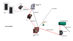
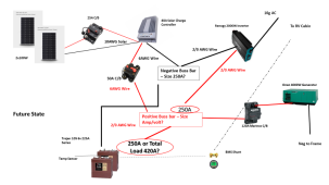
1648599505644.png 1648599542077.png
 
1. Treat bus bars like wire. This means the fuse must be the weak point. If you are going to have a 250A fuse then you need bus bars that can handle more than that. Both the positive and negative bus bars should be the same. 300A or more are needed in this case.
2. If you have no loads but you are charging with both solar and generator then 40A + 120A = 160A going to the batteries. If you have no charging but you are using the inverter at max then there is 200A going from the batteries. So 200A is the largest current through the wires. So the main battery fuse should be 250A. If you were to also have a DC fuse box that might pull, for example, 50A then that's up to 250A of load max and you would need a 300A main battery fuse (and then 350A or larger bus bars).
3. If you just have the inverter as the only load on the batteries at 200A then 2/0 between the batteries and inverter is fine. If you might also have DC loads plus the inverter for a total of 250A then 4/0 would be prudent between the batteries and bus bars. 2/0 could still be used from the bus bars to the inverter but it wouldn't hurt to both in 4/0 assuming the inverter can accept 4/0.

BTW - how did you choose a 120A breaker for a 4000W generator? 4000W at 12V is 333A.
 
BTW - how did you choose a 120A breaker for a 4000W generator? 4000W at 12V is 333A.
The 120A breaker is courtesy of Forest River. I was quoting what they "engineered". It's a rat's nest on the frame., so it's possible there is another breaker inline too. Scary nonetheless.

Thank you for your thoughtful responses.
 
A 120A breaker on a 12V line limits you to 1440W. Seems odd to limit the generator to about 1/3 of its rating.
 
1. Treat bus bars like wire. This means the fuse must be the weak point. If you are going to have a 250A fuse then you need bus bars that can handle more than that. Both the positive and negative bus bars should be the same. 300A or more are needed in this case.
2. If you have no loads but you are charging with both solar and generator then 40A + 120A = 160A going to the batteries. If you have no charging but you are using the inverter at max then there is 200A going from the batteries. So 200A is the largest current through the wires. So the main battery fuse should be 250A. If you were to also have a DC fuse box that might pull, for example, 50A then that's up to 250A of load max and you would need a 300A main battery fuse (and then 350A or larger bus bars).
3. If you just have the inverter as the only load on the batteries at 200A then 2/0 between the batteries and inverter is fine. If you might also have DC loads plus the inverter for a total of 250A then 4/0 would be prudent between the batteries and bus bars. 2/0 could still be used from the bus bars to the inverter but it wouldn't hurt to both in 4/0 assuming the inverter can accept 4/0.
A 120A breaker on a 12V line limits you to 1440W. Seems odd to limit the generator to about 1/3 of its rating.
I'd like to increase the 120A breaker to handle more of the 4000W Generator. The pos/neg wires seem under-sized; maybe they are marine-rated since they seem somewhat flexible. We use the generator sparingly for occasional microwave use, hair dryer, to charge electronics and A/C. We do charge batteries some, but the solar works so well in the current state.

Currently, the DC loads are typical/basic items such as lights, water pump, radio, USB charging port (2), and awning once setup for camping. CO2 monitor Adding the 2000W inverter (dedicated AC outlet) for coffee, charging/using laptops-monitor-dock, and limited TV in the evening. Inverter would be turned off when not in use (remote). I know there would be some stand-by draw.

From your info in #1 - #2 - #3 above, I think I will lean towards the following:
  • 350A for the bus bars
  • 300A main battery fuse
  • 4/0 between batteries & bus bars and 4/0 to inverter (if it can handle)
I have 2 Trojan 105 6v 225A batteries wired in series. Would the battery jumpers need to be upgraded?

I really appreciate your input. I've learned a lot.
 
Last edited:
I think you missed a component. You are not charging directly from the generator. You have some sort of charger. Possibly it is a converter or part of your inverter. I doubt it is 120a either way.

The batteries are not going to accept the level of charge you have. Dual 6v lead acids will take about 50a at first, but taper off to about mid 20s as they fill up. If you try to push more you will just boil the batteries and harm them over time. I have a 70a charger and about 25a solar charge ability. It does not put 95a in battery. The battery takes what it can and the chargers are smart enough not to boil batteries.

Wire size depends on load AND distance. There are plenty of charts online.

Skip those cheap CB in your diagram and get regular style that breaks both sides (+ and -) in a box (I believe that is code to break both + and -). I also put one on each side (pv to SCC and SCC to batteries) because I wanted ability to shut off SCC. Just be sure to turn off PVV first and on last.

Fuses are important. 250a for main battery cables/inverter, 50a for SCC (this is not the CB, but an actual fuse at the buss bar) because you have 40a SCC.

I just finished a 400w install on my RV so this all comes from my design and experience. I used strut channel to mount panels to with tilt brackets. I am running 2S2P to a Victron 100/30. 25a breaker for panels to SCC, 40a breaker from SCC to 40a fuse at buss bar on 6awg wire. Batteries are 2-6v 210ah with 1/0 to 250a buss bars. Short wires from buss bars to fuses. 250a fuses for inverter and generator wires. 40a fuse for SCC. I have 1200w inverter, peak at 2000w.

You notice the SCC has both a breaker and fuse. This is because the breaker does nothing for you if you get a short between it and the battery, which tends to be about 10ft. Always fuse close to the battery. The CB for the SCC is really just a disconnect, so it just needs to be the same size as fuse or larger. Will missed that in his design diagram.

In winter without tilting I am seeing low 300w, so about 75 to 80% efficiency. 4-HQST 100w compact panels. Tilting improves a lot. I can cover quite a bit of a panel before it impacts output. HQST has diodes that seem to work well.
 
Last edited:
I think you missed a component. You are not charging directly from the generator. You have some sort of charger. Possibly it is a converter or part of your inverter. I doubt it is 120a either way.
I did indeed miss this piece. The 120A CB for the generator positive is only for starting the generator. There is a WFCO Converter.

40A SCC has the "cheap" 50A CB. The PV are not mounted to the RV. There is a manual disconnect on the outside. The PV positive has a CB to the SCC.

Thank you for your input. I'm still flushing out the wires, fuses, etc. setup for the inverter.
 
Back
Top