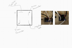
This might be the newbie in my but I am really confused about something I am seeing with my DIY wind generator. When there is no resistance, it is not hooked up to the battery, I get the motor to run at about 800 to 1000 RPM, with about a 10mph wind. Once a 12V battery is attached the motors slow down to about 300 to 400 RPM, which I am assuming is due to resistance and metering of the voltage to the batteries. I am using a very simple setup, motor, with a full-wave rectifier, connected to the battery. However, when I then hooked up a 24 V, well it isn't fully charged to 19.9V, battery to see what would happen the motors speed up to match the voltage and runs at the 800 to 1000RPM. I do not change anything on the system other than the battery setup. My understanding of wind generators should be that they run at the speed of the wind with resistance and motors produce energy related to the speed. I am using Permanent Magnet DC Generator with a Current: 1.5A continuous, 2.5A max at about 1200 RPM for 13.8VDC. By the way, I am not seeing any voltage near 1.5A at 1000RPM, I am at .02A.
You are using an out of date browser. It may not display this or other websites correctly.
You should upgrade or use an alternative browser.
You should upgrade or use an alternative browser.
Wind Power Generation
- Thread starter papinida
- Start date
svetz
Works in theory! Practice? That's something else
Welcome to the forums!
Getting power out of the turbine requires work, so I'd expect the rotor to turn slower, forcing the wind to apply more force to the blades.
You might also want to read: https://www.solacity.com/small-wind-turbine-truth/
Getting power out of the turbine requires work, so I'd expect the rotor to turn slower, forcing the wind to apply more force to the blades.
You might also want to read: https://www.solacity.com/small-wind-turbine-truth/
svetz
I agree getting power requires work. However the issues is if the wind remains constant, I am doing this in a controlled environment, and I change the battery voltage it changes the speed at which the blades turn. This changes seems to be inverse as well larger battery higher speeds.
I agree getting power requires work. However the issues is if the wind remains constant, I am doing this in a controlled environment, and I change the battery voltage it changes the speed at which the blades turn. This changes seems to be inverse as well larger battery higher speeds.
svetz
Works in theory! Practice? That's something else
I don't have a wind turbine or know that much about them. Most of the charts I see show constant power for constant wind speed and don't say boo about rpm. RPM probably isn't important...it's probably torque.
Just thinking out of the blue... as battery voltage increases the generator must increase the torque to keep pushing power into into it... otherwise power wouldn't be constant. For more torque you need more air-flow or lower RPM. So, what I'd expect is to see at a constant wind speed is lower RPMs as voltages increase.
A larger battery wouldn't make a difference except that it would take longer for a battery voltage change to occur. Guess I'd have to see your experimental numbers to comment more on it.
Last edited:
Hedges
I See Electromagnetic Fields!
- Joined
- Mar 28, 2020
- Messages
- 20,508
There will be some load and RPM where power delivered is maximum. No load highest speed and shorted output not turning will deliver zero power, with a curve in between.
You could load the DC port with a variable resistor (alligator clips to tap off a string of resistors or low voltage lightbulbs.) If you made a circuit what switched PWM like a light dimmer, that might work.
If you got a variac (adjustable transformer) and put it between the permanent magnet alternator and the rectifier, you could alter operating voltage and load. It may have 3-wires so you'd have to leave one open and only use two.
Commercial charge controllers would use a switching power supply to set one operating voltage at the source, another at the battery.
I think some are set for constant voltage, and vary the current drawn to maintain it.
Keith C
Ahhh, the sharks have him.
Please don't refer to your generator as a 'motor' as you're using it as a 'generator'. It gets confusing when you jump back and forth with the terminology. It's fine to say I'm using motor X as a generator but then stick with generator.
Your generator has a rated output voltage depending on its construction something around 14V. That means it can never provide enough voltage to charge a 24V battery so it's not. That means it isn't being loaded at all so it will free-wheel at high speed.
Your generator has a rated output voltage depending on its construction something around 14V. That means it can never provide enough voltage to charge a 24V battery so it's not. That means it isn't being loaded at all so it will free-wheel at high speed.
Thank you and my apologizes I will not switch my terminology. The generator can do both 12V and 24V according to it specifications, it is from wind stream power.
I went back after reading the post and I was concerned that I was not on the curve due to the RPMs being only between 300 to 400 rpm, once the load was applied. The curve for at 13.8VDC starts at 400RPM so to make sure I was well on the curve I attached a drill and uped the rotation to 800 to 1000rpms, which at 1000rpm should be 1amp. I am still only in the mA, I am now at 250mA, which is a vast improvement but still seems incorrect. I am using a bayite DC 6.5-100V 0-100A LCD Display Digital Current Voltage Power Energy Meter Multimeter Ammeter Voltmeter with a 75mV 100A shunt and went back to a 12V battery pack and made sure it was not full charged and even put an invertor on it and plugged in a lamp to make sure there was a current draw. Has anyone seen this issue.
I went back after reading the post and I was concerned that I was not on the curve due to the RPMs being only between 300 to 400 rpm, once the load was applied. The curve for at 13.8VDC starts at 400RPM so to make sure I was well on the curve I attached a drill and uped the rotation to 800 to 1000rpms, which at 1000rpm should be 1amp. I am still only in the mA, I am now at 250mA, which is a vast improvement but still seems incorrect. I am using a bayite DC 6.5-100V 0-100A LCD Display Digital Current Voltage Power Energy Meter Multimeter Ammeter Voltmeter with a 75mV 100A shunt and went back to a 12V battery pack and made sure it was not full charged and even put an invertor on it and plugged in a lamp to make sure there was a current draw. Has anyone seen this issue.
Hedges
I See Electromagnetic Fields!
- Joined
- Mar 28, 2020
- Messages
- 20,508
100A shunt, looking for 1.0A but reading 250 mA.
What are the accuracy and range ratings of that meter? You're trying to use at at 1% of full scale or below.
I wouldn't expect it to be off by a factor of 4 but you never know.
You're trying to see 1A at 12V or 12W, something like that.
Can you get a 10 ohm or 20 ohm resistor, something in the 10W to 20W range?
Wire a bunch of resistors together if needed, like 10, 1/8W 100 ohm resistors in parallel.
Measure resistance, then attach generator and measure voltage.
Otherwise, sounds like the generator doesn't deliver current claimed.
Last edited:
Thanks. I even verified the shunt settings on the meter that it was set correctly. The specifications are:
Working voltage: DC 6.5 ~ 100V
Measuring Accuracy: 1%
Power Consumption: 0.2W
Measurement speed: 2 times/s
Test Range and Display format:
1. Active Power test range: 0~10kW
2. Energy test range: 0~9999kWh
3. Voltage test range: DC 6.5~100V
4. Current test range: 0~ 100A
Working voltage: DC 6.5 ~ 100V
Measuring Accuracy: 1%
Power Consumption: 0.2W
Measurement speed: 2 times/s
Test Range and Display format:
1. Active Power test range: 0~10kW
2. Energy test range: 0~9999kWh
3. Voltage test range: DC 6.5~100V
4. Current test range: 0~ 100A
Keith C
Ahhh, the sharks have him.
I agree with Hedges. Put a resistor in series. Measure the voltage across it and simply use Ohm's Law to check your output.
RCinFLA
Solar Wizard
- Joined
- Jun 21, 2020
- Messages
- 3,559
Permanent magnet alternators have a quite complicated rpm-torgue-output voltge-output current relationship. Change one item effects the other items.
For a given size, the more torque at rpm's the more potential power it can generator. Easy enough at this point. To get the full potential power at a given mechancial torque you need to present a particular electrical load which needs to change for different rpm's. For wind or hydro the rpm's will drop when electrically loaded so there will be a optimum maximum power load point depending on mechanical input torque and its rpm's.
For a given size, there is a limited stator winding area for wiring turns. You can have less turns of larger gauge wire or more turns at smaller gauge wire. You can burn out the stator windings with enough rpm's and load on a high turn/small gauge wire alternator. The wire gauge needs to be optimum for a targeted voltage-current range. So you need to select an alternator design based on its target voltage-current range.
Then there are rectifier diodes. They have a current handling maximum and a breakdown voltage maximum. With a high turns/small gauge wire stator with enough rpm's and light electrical load you can exceed the breakdown voltage of the diodes. Too much load with high rpm's on low turns/large gauge wire stator can burn out diodes with too much current.
All PMA systems have bounds they must be kept within to prevent damage. Playing outside these bounds can damage the PMA.
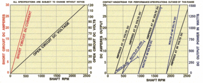
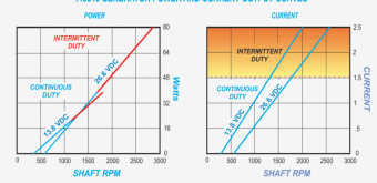
The below chart are only for a particular amount of stator turns for a given size PMA. You need to know its maximum voltage and current limits before starting to play with various rpm's and loading to stay within safe bounds.

I took the wind out of the equation for now and hooked up a drill to the generator so I could really get some rpms on the system. I have an RPM gauge that I am using and at full drill power which is was well over 1200rpm I never got past .5amps, with or with the 10ohm resistor put in the system.
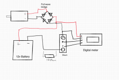
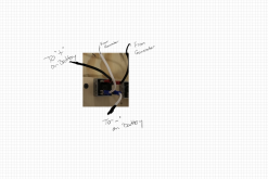
Here is the wiring diagram that I am using as well. I also tried putting the 10ohm resistor in the circuit as well. But even with that never got past mA range.
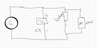
I purchased some 10 ohms 10 W resistors and measured the resistance to be 37ohms, so using ohms law says it should be 0.4 amps at 12 volts. I then plugged it into a 12.4 volt source with the 10-ohm resistor according to the below really bad diagram the meter read 12 volts and the motor spun, which I am thinking was how I was supposed to do that:
Here are the curves that they gave me as part of generators, which is why I am really stumped:
Here is the wiring diagram that I am using as well. I also tried putting the 10ohm resistor in the circuit as well. But even with that never got past mA range.

I purchased some 10 ohms 10 W resistors and measured the resistance to be 37ohms, so using ohms law says it should be 0.4 amps at 12 volts. I then plugged it into a 12.4 volt source with the 10-ohm resistor according to the below really bad diagram the meter read 12 volts and the motor spun, which I am thinking was how I was supposed to do that:

Here are the curves that they gave me as part of generators, which is why I am really stumped:

Hedges
I See Electromagnetic Fields!
- Joined
- Mar 28, 2020
- Messages
- 20,508
If you wired the rectifier as show, there's your problem!
??
Keith C
Ahhh, the sharks have him.
Well, from the right side photos the wire colors are suspect but since we don't see where they go they could be correct.
Could you explain why you're even using a bridge rectumfrier? You label the generator with polarized outputs. The factory curves list "DC" all over them.
Could you explain why you're even using a bridge rectumfrier? You label the generator with polarized outputs. The factory curves list "DC" all over them.
Yes Keith you are correct they are DC generators. I am using the bridge rectifiers because 1) there are two generators 2) one rotates one direction and one rotates the opposite direction 3) I am not using a charge controller. The color of the wires is the same as the color on the generators so I did not confuse them. Yes, I should have changed the white to red on the other side of the rectifier. Here is a new picture with it labeled.
If it is not the wiring of the rectifier what else could it be after testing with the resistors I am still at a loss and it doesn't seem like the generators are bad.

If it is not the wiring of the rectifier what else could it be after testing with the resistors I am still at a loss and it doesn't seem like the generators are bad.
Keith C
Ahhh, the sharks have him.
So you're trying to 'diode isolate' the two generators. I hope you don't use both while sleuthing out this problem.
You should be using only one diode not a bridge. Put the one diode in the + lead from the motor to the + on the battery.
According to your generator curves in 13.8V mode it should put out 1Amp at 1000rpm at 13.8A.
Rewiring your bridge to only use a single diode. The input should be either AC ~ terminal and the output the + terminal. That gets you one of the four diodes.
That diode costs you 0.8V of waste loss so you'd be down to 13.8V - 0.8V or 13V.
13V / 1A = 13ohms Come up with a 13 ohm resistor.
Hook it from the bridge + terminal and the other side to the (-) terminal of the generator.
Use your (variable speed) drill and your rpm meter and run the generator at 1,000rpm.
Does it put out 1A +/- about 0.1A?
If yes it works.
If no it fails to meet the spec.
Keith - thank you for the help. I pulled everything back to motors and tried the various things you recommended. It looks like I was able to get the motors to output close to 1amp using the bridge terminal as a diode. I ran the motor at 1000rpms and used an RPM new meter setup to get closer. I now have a different problem, most small wind generators run 60 to 90 RPM and I need 1000 RPMs to get this thing to produce any amps, which I don't think is good. Seems like I might just have a paperweight.
Any suggestions on new generators that might work? or an alternative method to get to a usable voltage/amp?
I do have a current restriction, which is a limited space since the nacelle I made fits a 2.5" diameter generator, I do have a good amount of length available. So could do stages. If I knew how to build one I would do it, but if someone knows of one on the market or a custom shop that would be awesome.
You all have been very helpful thank you!!!!!
Hedges
I See Electromagnetic Fields!
- Joined
- Mar 28, 2020
- Messages
- 20,508
I tried the same thing using a stepper motor, which has many poles so lower RPM for same frequency, but also got very little current.

 www.umaelectrocontrols.com
Of course, gear drive or belt/chain drive is also done. But then you need more torque.
Here's a 100 RPM generator:
Here's a turbine that says 800 RPM. A big part of that would be blade design, if it is an airfoil and not just a drag device.

 greencoast.org

Stepper Drive - AC Stepper Motor Drive Manufacturer from Ahmedabad
Manufacturer of Stepper Drive - AC Stepper Motor Drive, DC Stepper Motor Drive, Stepper Motor offered by UMA Electro Controls, Ahmedabad, Gujarat.
Of course, gear drive or belt/chain drive is also done. But then you need more torque.
Here's a 100 RPM generator:
All Products : WINDPMG!, Low RPM Wind Permanent Magnet Generator
WINDPMG! : All Products - WINDPMG50 Flange Dump Load Hand Generator Parts WINDPMG10 WINDPMG400 wind generator, Wind Permanent Magnet Generator, wind PMG, coreless wind PMG, coreless wind generator, shop, online shopping, store
www.windpmg.com
Here's a turbine that says 800 RPM. A big part of that would be blade design, if it is an airfoil and not just a drag device.

13 Best Home Wind Turbines in [currentyear]: Generate Electricity at Home
Are you tired of the ever-rising electricity bills? Wind energy is an excellent option that can ensure a significant reduction in your power bills. Let's explore together the many home wind turbines available for use
Similar threads
- Replies
- 1
- Views
- 281
- Replies
- 0
- Views
- 226
- Replies
- 3
- Views
- 279
- Replies
- 38
- Views
- 2K


