diy solar

diy solar

Wire gauge for JBD 150a bms

frthompson

New Member
Joined
May 29, 2021
Messages
62
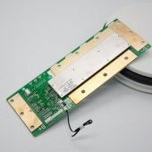
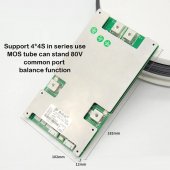
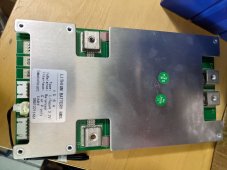
I am building 2 12v 280ah 4s batteries each with a jbd 150a bms that will be connected in parallel. Each bms has two screw terminals for the B- and two for the C- connections. I am not counting on using the full capacity of the bms but seems reasonable to design the wire for 150a since that's the advertised capacity of the bms. From pictures of other installs I've seen it seems its considered best to use both B- and C- terminals with the two wires then going to a single terminal ring connector for each. So my question is what gauge wire to use if there are two wires for the B- and two for the C- connections with given the the rated capacity of the bms is 150a? The maximum draw I expect from the two batteries in parallel would be 100-200 amps if I run the microwave or air conditioner in my rv (but not at the same time!).
 
The NEC current rating for conductors is extremely conservative, accounting for variables which don't exactly cross reference to use in battery based applications due to the short runs typically associated with them, but a useful guide none the less.

When used in conjunction with a voltage drop calculator it can be seen that over a short distance, voltage drop is extremely low, in the example below a #3 AWG with 200A at 12V over a 1 foot run is only 0.032V, so keeping runs short allows for smaller gauge. Being that current is inversely proportional to voltage, at higher nominal voltages, the voltage drop will be further reduced.

As a general rule it best to use the highest gauge possible and keep the runs as short as possible particularly in low voltage applications.


Screenshot_2021-08-10-09-53-02.png
 
I'm building exactly the same as you. Six of eight batteries just showed up today and one BMS. I plan to use 2x 4awg for the runs to/from the BMS and 2awg for the other side of the battery. I don't plan to fuse the batteries separately. My largest load is a 2kw PSW inverter so I won't hit the full 300A. The current batteries (4x FR 224AH AGM) are fused @ 250.

As far as the BMS goes I order 2 150A JBD bms units separate to the 280ah batteries as I also order 8x 150AH cells. When I order the 280's I also order 2x 150A JBD BMS's from that supplier. The BMS units are two different style although all are supposed the JBD 4s 150A units. The longer style is from the 280Ah cell order
 

Attachments

  • Hf94268b33d264480973e136ca88be79ag.jpg
    Hf94268b33d264480973e136ca88be79ag.jpg
    100.6 KB · Views: 44
  • 4S-12V-150A-BMS-JBD-smart-BMS-60A-80A-100A-120A-Li-ion-LifePo4-18650-Lithium (2).jpg
    4S-12V-150A-BMS-JBD-smart-BMS-60A-80A-100A-120A-Li-ion-LifePo4-18650-Lithium (2).jpg
    121.3 KB · Views: 44
The longer one is the JBD 150A. It's the V1.5 board, but does not have the heater ports which I thought all V1.5 boards had - at least mine does.

The smaller one says 100A.
 
The longer one is the JBD 150A. It's the V1.5 board, but does not have the heater ports which I thought all V1.5 boards had - at least mine does.

The smaller one says 100A.
I just grabbed pics of the net for both but they are the styles I have. Both of mine are the 150A versions of these. The longer board is a newer version? It'll be a bit harder to work into a battery pack as it's longer than 4 280ah cells fitted as a block
 
I have two 150A JBD BMS arriving from the JBD store on AliExpress next week so I'll see what they look like.
 
The longer board is a newer version?
The longer board is the JBD 150A BMS. They have updated the versions over time, but the basic layout has remained. The smaller ones are 100A or 120A units unless something has changed. Perhaps the vendor did not have the correct picture associated with the 150A BMS.

I'm using three 10AWG wires each to B- and C- and a single 10AWG to B+
 
Here's a picture of the actual board I have in hand that is not the longer format. It says 150a on the label.
 

Attachments

  • PXL_20210814_162734948.jpg
    PXL_20210814_162734948.jpg
    237.3 KB · Views: 60
Are you sure that's a JBD BMS? The part number is usually printed on the label and starts with JBD-xxxxxx.

IDK, I just haven't seen that before, but who knows........
 
I powered up the smaller sized (physically) of the two BMS units and in the parameters section of the app it reports as JBD-SP04S028-L4S-150A-B-U

I did receive the final 2 batteries but the 2nd BMS (longer style) was missing from the shipment so I still don't know what the 4th BMS will look like. My Alibaba order from Exliporc shows it as a Daly and the instructions also have Daly on them. I'll continue to be confused I guess :)
 
The 100A and 120A BMS looks like they have 3 wires each for B- ans C- and the wires looked soldered on? For the 150A board, there are only 2 spots for wires for each vs 3. Does it come with a bolt to connect the wire? Those that have installed do you just put a lug on wire and bolt them down or what is the best way to attach the wires to the B- and C- connections on the BMS?
 
150 amps / .8 fuse headroom = 187.5 fault amps
2x 6 awg is equivalent to 1x 3 awg.
3 awg pure copper with 105C insulation is rated for 180 fault amps.
With a 180 amp fuse you would be pushing it to the razor's edge.

2x 4 awg of the same specs would give some breathing room.


Same Question, slightly different batteries/BMS. I'm building 2 batteries with 4 x 304 EVE cells through a JBD 4s 200A BMS (Model SP04S034-FET V 1.3 board), and about to purchase the wire for the B-/C- connections internal to the battery (casing is an ABS battery box).

Wanting to use high strand count Silicone wire (3200 strands @ .08mm each) with 200C rating for the mechanical flexibility, and keep the lengths as short as possible inside the battery. This is similar to what is attached to a lot of commodity BMS's.

Middle of the table for Up to 3 conductors in a sheath (see below) since I'll have braided wire sleeve covering it, shows each #6 AWG conductor can carry 84A.

So....

200A / .8 fuse headroom =250 fault amps

3 x 6 AWG = 3 x 84A= 252 A total capacity

Any other or better ideas?

1635876423081.png
 
Same Question, slightly different batteries/BMS. I'm building 2 batteries with 4 x 304 EVE cells through a JBD 4s 200A BMS (Model SP04S034-FET V 1.3 board), and about to purchase the wire for the B-/C- connections internal to the battery (casing is an ABS battery box).

Wanting to use high strand count Silicone wire (3200 strands @ .08mm each) with 200C rating for the mechanical flexibility, and keep the lengths as short as possible inside the battery. This is similar to what is attached to a lot of commodity BMS's.

Middle of the table for Up to 3 conductors in a sheath (see below) since I'll have braided wire sleeve covering it, shows each #6 AWG conductor can carry 84A.

So....

200A / .8 fuse headroom =250 fault amps

3 x 6 AWG = 3 x 84A= 252 A total capacity

Any other or better ideas?
I double checked and got the same answer as you.
Pure copper 6 awg wire with insulation rated for 105C has an ampacity rating = 120 amps
120 amps * .7 bundle factor = 84 amps
84 amps * 3 conductors = 252 amps
 
I double checked and got the same answer as you.
Pure copper 6 awg wire with insulation rated for 105C has an ampacity rating = 120 amps
120 amps * .7 bundle factor = 84 amps
84 amps * 3 conductors = 252 amps

Thank you!
 
Next question, what is the correct size lug for 3x 6AWG. I think this is about between a 1 and 2 guage? Is the an app for that?:giggle:
 
Back
Top