Sun_Dried_Toad
New Member
- Joined
- Sep 6, 2020
- Messages
- 81
Due to a small mistake on my suppler's end, I was unable to install my solar array this weekend as planned. instead, I'm wiring in everything else.
I live in a stick built, house on foundation. We have (soon to be "had") standard grid power. We have 240V available coming in from the grid, via two individual 120 cables from the meter, attached to two sides (lugs) of our power distribution (breaker) panel.
We have central HVAC which runs on 240V. We also have a clothing dryer which runs on 240V. THOSE ITEMS WILL NOT BE MOVED TO THE NEW, SOLAR SYSTEM. they will remain on the grid system. As such, we will only need 120V in our new breaker panel for all 9 of our circuits inside our home.
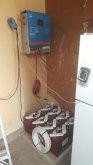
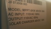
My new breaker panel will receive power (120VAC) from the "Bright" or "BR SOLAR" brand charge controller. Model: MPPT-5KW 48VDC 60A
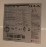
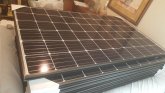
EDIT: this system is powered by 8 QCELL panels, 305 watts each.
despite what the front of the charge controller says, it puts out 120v single phase AC. it does not put out 240v. this was verified by my supplier. prior to shipping my system out, he connected it all, and ran it, to ensure everything was working. I don't know if he had to modify it to 120 or what. all I know is that he told me it makes 120v. upon arrival, I saw the front of the controller stated 240v. I contacted him, and he assured me it makes 120v.
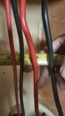
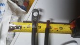
the lugs for the "AC out" terminals on my charge controller look like they will only accept 10AWG wire. This means my entire home's power supply must travel through 3 feet worth of 10AWG wire to get to my 60A breaker, and through it, into my power distribution (breaker) panel. is this acceptable? Looking at the cable that comes in from the pole, through my meter, and into my existing grid supplied breaker box (via a 60A main breaker) is probably #2 AWG wire/cable.
let me itemize my EXISTING GRID breaker panel for clarity:
there are TWO 120V hot cables coming in. each ties to one of two lugs. we will refer to these as North and South lug. of course, there is also one common.
the ONLY breakers that receive power from both North and South lugs are my HVAC and clothes dryer. THESE ARE NOT PART OF THE SOLAR BOX.
that said, we will discuss only the 120v breakers that will be in the new box.
I have 3 tandem breakers in the old, grid box. in the new box, these will be slimline style. same thing, different shape. two circuits on one breaker clip.
I will refer to the tandem/slimline breakers as A&B of its clip in panel number.
1A. Our wine room ceiling fan/light, Guest room east wall outlets
1B. kitchen refrigerator, dishwasher
2. obsolete/deleted/omitted - (clothing dryer) shares breaker clip in #4 for 240v
3A. clothing washing machine
3B. Laundry room light, dining room fan/light, 120v outlet behind love seat.
4. obsolete/deleted/omitted - (clothing dryer) shares breaker clip in #2 for 240v
5A. kitchen LED light, Microwave.
5B. Hallway lights, main bathroom vanity lights & overhead (ceiling) socket intended for heat bulbs (usually has CFL "regular" bulbs in it)
6. living room fan/light, west side garage outlets, garage door opener, garage fluorescent light ballast, garage refrigerator.
7. fish tank pump/filter in dining room, master bedroom fan/light, master bathroom vanity lights.
8. outlets on east wall of garage, oven/range vent hood, garage chest freezer SEE NOTES BELOW ON #8 OTHER ITEM
9. Obsolete/Deleted/Omitted - OLD ELECTRIC OVEN/RANGE. WE NOW HAVE A GAS OVEN RANGE. (shares slot #11 for 240V)
10. MAIN BREAKER for incoming power 60Amp. shares slot #12 to energize North and South lugs with 120v each.
Special notes about #8 breaker: something attached to this breaker causes the HVAC system to shut down when flipped to "off" position. IT IS DOES NOT SUPPLY POWER TO THE OUTDOOR CONDENSER/COMPRESSOR UNIT. It is a 120v circuit, the compressor/condensor unit is 240v. when the #8 breaker is tripped, or turned off, the 240v to the condenser/compressor is STILL LIVE. this stated, I think that the #8 breaker controls the indoor unit. The evaporator coil, gas furnace and blower unit that distributes HVAC air throughout our home, is mounted in our attic. I think that it has a safety kill switch that causes the contractor coil to drop out on the outdoor compressor/condenser unit to prevent evaporator freeze up and compressor burn out.
there are a few small circuits not listed, but they are just some mostly unused outlets and our guest bedroom fan/light. we just didn't get them listed in our map when we made it. they are on the above listed circuits, just not in the list.
My new panel has 4 less slots. it is an 8 breaker panel. #6 and #8 are reserved for the 60 amp main breaker, so it is actually a 6 breaker panel.
This could change, but here goes a basic/generic list of the new panel:
1a. wine room fan/lights, guest room east wall outlets
1b. kitchen fridge, dish washer
2. living room light/fan, west garage outlets, garage refrigerator, garage door opener, fluorescent ballast light
3a. clothes washing machine
3b. laundry room light, dining room light/fan, 120v outlet behind love seat
4. East wall garage outlets, garage chest freezer, Range hood, SEE NOTES ON #8 ABOVE
5a. kitchen LED light, microwave
5b. hallway lights, main bathroom vanity & overhead lights.
6 & 8. Main 60amp incoming power breaker. only 1 leg of 120v comes out of my charge controller. I plan to split that one leg into a "Y" and feed the split leg into both lugs of the double throw 60 amp breaker mounted in slots #6 & #8 to energize both lugs (North and South) of the entire new solar dedicated breaker box.
FINALLY, my questions:
1. is there any reason that I cannot depend upon my charge controller to supply my home with enough power?
2. Can I split my 120v coming out of my controller into a "Y" to feed both sides of my 60a main breaker?
3. if 2 is correct, will my 60a breaker work as it should?
4 is 10AWG wire/cable coming from my "AC out" lugs on charge controller to my 60a main breaker in new box acceptable, or is it too small?
FINAL BIT OF INFO FOR REFRENCE:
on an average day, if we turned everything that we normally use in our house on at the same time, we would use approx 2,800KW in an hour.
we never do this.
my wife and I live alone, and are child-free by choice.
at any given time, we have running:
chest freezer
garage refrigerator
kitchen refrigerator
and we may also have a few lights, our television, her fish tank pump, and a few ceiling fans.
most other things are seldom. we run dish washer when at work, so few other loads. clothes washer on Mondays, blender for few seconds in the morning, maybe her playstation once a week for an hour our two.
being just the two of us, we don't really use much electricity. I mean we do... but it's generally a light load.
I live in a stick built, house on foundation. We have (soon to be "had") standard grid power. We have 240V available coming in from the grid, via two individual 120 cables from the meter, attached to two sides (lugs) of our power distribution (breaker) panel.
We have central HVAC which runs on 240V. We also have a clothing dryer which runs on 240V. THOSE ITEMS WILL NOT BE MOVED TO THE NEW, SOLAR SYSTEM. they will remain on the grid system. As such, we will only need 120V in our new breaker panel for all 9 of our circuits inside our home.
My new breaker panel will receive power (120VAC) from the "Bright" or "BR SOLAR" brand charge controller. Model: MPPT-5KW 48VDC 60A
EDIT: this system is powered by 8 QCELL panels, 305 watts each.
despite what the front of the charge controller says, it puts out 120v single phase AC. it does not put out 240v. this was verified by my supplier. prior to shipping my system out, he connected it all, and ran it, to ensure everything was working. I don't know if he had to modify it to 120 or what. all I know is that he told me it makes 120v. upon arrival, I saw the front of the controller stated 240v. I contacted him, and he assured me it makes 120v.
the lugs for the "AC out" terminals on my charge controller look like they will only accept 10AWG wire. This means my entire home's power supply must travel through 3 feet worth of 10AWG wire to get to my 60A breaker, and through it, into my power distribution (breaker) panel. is this acceptable? Looking at the cable that comes in from the pole, through my meter, and into my existing grid supplied breaker box (via a 60A main breaker) is probably #2 AWG wire/cable.
let me itemize my EXISTING GRID breaker panel for clarity:
there are TWO 120V hot cables coming in. each ties to one of two lugs. we will refer to these as North and South lug. of course, there is also one common.
the ONLY breakers that receive power from both North and South lugs are my HVAC and clothes dryer. THESE ARE NOT PART OF THE SOLAR BOX.
that said, we will discuss only the 120v breakers that will be in the new box.
I have 3 tandem breakers in the old, grid box. in the new box, these will be slimline style. same thing, different shape. two circuits on one breaker clip.
I will refer to the tandem/slimline breakers as A&B of its clip in panel number.
1A. Our wine room ceiling fan/light, Guest room east wall outlets
1B. kitchen refrigerator, dishwasher
2. obsolete/deleted/omitted - (clothing dryer) shares breaker clip in #4 for 240v
3A. clothing washing machine
3B. Laundry room light, dining room fan/light, 120v outlet behind love seat.
4. obsolete/deleted/omitted - (clothing dryer) shares breaker clip in #2 for 240v
5A. kitchen LED light, Microwave.
5B. Hallway lights, main bathroom vanity lights & overhead (ceiling) socket intended for heat bulbs (usually has CFL "regular" bulbs in it)
6. living room fan/light, west side garage outlets, garage door opener, garage fluorescent light ballast, garage refrigerator.
7. fish tank pump/filter in dining room, master bedroom fan/light, master bathroom vanity lights.
8. outlets on east wall of garage, oven/range vent hood, garage chest freezer SEE NOTES BELOW ON #8 OTHER ITEM
9. Obsolete/Deleted/Omitted - OLD ELECTRIC OVEN/RANGE. WE NOW HAVE A GAS OVEN RANGE. (shares slot #11 for 240V)
10. MAIN BREAKER for incoming power 60Amp. shares slot #12 to energize North and South lugs with 120v each.
Special notes about #8 breaker: something attached to this breaker causes the HVAC system to shut down when flipped to "off" position. IT IS DOES NOT SUPPLY POWER TO THE OUTDOOR CONDENSER/COMPRESSOR UNIT. It is a 120v circuit, the compressor/condensor unit is 240v. when the #8 breaker is tripped, or turned off, the 240v to the condenser/compressor is STILL LIVE. this stated, I think that the #8 breaker controls the indoor unit. The evaporator coil, gas furnace and blower unit that distributes HVAC air throughout our home, is mounted in our attic. I think that it has a safety kill switch that causes the contractor coil to drop out on the outdoor compressor/condenser unit to prevent evaporator freeze up and compressor burn out.
there are a few small circuits not listed, but they are just some mostly unused outlets and our guest bedroom fan/light. we just didn't get them listed in our map when we made it. they are on the above listed circuits, just not in the list.
My new panel has 4 less slots. it is an 8 breaker panel. #6 and #8 are reserved for the 60 amp main breaker, so it is actually a 6 breaker panel.
This could change, but here goes a basic/generic list of the new panel:
1a. wine room fan/lights, guest room east wall outlets
1b. kitchen fridge, dish washer
2. living room light/fan, west garage outlets, garage refrigerator, garage door opener, fluorescent ballast light
3a. clothes washing machine
3b. laundry room light, dining room light/fan, 120v outlet behind love seat
4. East wall garage outlets, garage chest freezer, Range hood, SEE NOTES ON #8 ABOVE
5a. kitchen LED light, microwave
5b. hallway lights, main bathroom vanity & overhead lights.
6 & 8. Main 60amp incoming power breaker. only 1 leg of 120v comes out of my charge controller. I plan to split that one leg into a "Y" and feed the split leg into both lugs of the double throw 60 amp breaker mounted in slots #6 & #8 to energize both lugs (North and South) of the entire new solar dedicated breaker box.
FINALLY, my questions:
1. is there any reason that I cannot depend upon my charge controller to supply my home with enough power?
2. Can I split my 120v coming out of my controller into a "Y" to feed both sides of my 60a main breaker?
3. if 2 is correct, will my 60a breaker work as it should?
4 is 10AWG wire/cable coming from my "AC out" lugs on charge controller to my 60a main breaker in new box acceptable, or is it too small?
FINAL BIT OF INFO FOR REFRENCE:
on an average day, if we turned everything that we normally use in our house on at the same time, we would use approx 2,800KW in an hour.
we never do this.
my wife and I live alone, and are child-free by choice.
at any given time, we have running:
chest freezer
garage refrigerator
kitchen refrigerator
and we may also have a few lights, our television, her fish tank pump, and a few ceiling fans.
most other things are seldom. we run dish washer when at work, so few other loads. clothes washer on Mondays, blender for few seconds in the morning, maybe her playstation once a week for an hour our two.
being just the two of us, we don't really use much electricity. I mean we do... but it's generally a light load.
Attachments
Last edited: