diy solar

diy solar

Wire Size, Have I got this CORRECT?

NelsonAC

New Member
Joined
Jul 10, 2021
Messages
8
The System:
Inverter: Growatt SPF 3000TL LVM-ES, max PV input voltage(VOC) 250VDC
Panels: 410watt, VOC=49.4V, Short Circuit Current=10.59A
Distance from array to inverter=30 ft

Currently have 5 panels in series for about 226V on a sunny day, read at Growatt Inverter.
Also read at Inverter shows about 1.8A on a sunny day.
Doing math, 226V x 1.8A = 406.8watts, make sense since it is close to my 410watt panels.


Have 4 unused #12 thhn/thwn 600v wire burred in conduit from a previous project. Originally calculated wire size for
10A at 250V at 30ft. , resulting in a pair of #12 wire would be fine for 5 panels in series. This was believing that there would be 10A.
Then when seeing the inverter showing 1.8A, I conclude that since I raised the voltage 5times (series connections), that the
ampere of the panel was reduce by an divider of 5.
CORRECT?

Am adding 5 more panels in series for a set up of 5series 2 parallel. Am I correct in assuming that I can still use the original pair of
#12 wires to carry voltage from array to inverter, instead of using another pair of #12 wires? CORRECT? Using 1 set of #12 would be
easier and less wiring.

Trying to understand some basic concepts. Any thoughts and comments are much appreciated.
 
Last edited:
Currently have 5 panels in series
Unless the temperature is *never* below 25deg C, that could be a problem.

5*49.4 = 247V. That leaves no margin for the voltage rise when it gets cold. The system is in danger of blowing out the MPPT.

Please review these two resources:
 
Unless the temperature is *never* below 25deg C, that could be a problem.

5*49.4 = 247V. That leaves no margin for the voltage rise when it gets cold. The system is in danger of blowing out the MPPT.

Please review these two resources:
Have not taken into account. Will review the resources and adjust. thankyou.
It still my be ok because the Maximum Power Voltage Vmpp=40.7V and
Electrical Data (NMOT) off of spec sheet has Voc=46.6 [46.6 x 5 = 233] Still not much room for voltage rise though.
 
Last edited:
Have not taken into account. Will review the resources and adjust. thankyou.
It still my be ok because the Maximum Power Voltage Vmpp=40.7V and
Electrical Data (NMOT) off of spec sheet has Voc=46.6 [46.6 x 5 = 233] Still not much room for voltage rise though.
Look up the voltage coefficient of your panels and figure your lowest temperature. That way you can be sure you are good.

As to your other question, I am jot sure I follow you. But..

Let's say you have a 30 volt, 10 amp panel. If you put 5 of then in series you would come up with 150 volts and 10 amps. If you took a second set of the same 5 panels and put them in series with the first you would have 150V at 20 amps.
I agree, not sure where I was going either.
 
Have not taken into account. Will review the resources and adjust. thankyou.
It still my be ok because the Maximum Power Voltage Vmpp=40.7V and
Electrical Data (NMOT) off of spec sheet has Voc=46.6 [46.6 x 5 = 233] Still not much room for voltage rise though.
Here is my rule of thumb:

If the array Voc x 1.25 is less than the max voltage on controller PV input... you are good for all the most extreme low temperatures.

If the Array Voc x 1.25 is greater than the max allowed voltage on the Controller PV input, then the calculations for voltage rise need to be done in order to be sure there is no calculation.

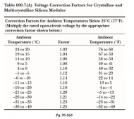
A second shortcut is to use the NEC table.

1635118078153.png

This table is calculated for a beta (Voc temp coefficient) of -0.40 %/deg C so it is very conservative. (The typical range of beta is ~-0.27 to -0.38). If this table says there is not a problem, it is probably safe. However, calculating using the panel's actual beta may allow configurations that the table would not. (Note that the NEC says the table should only be used if the panel beta is not available)
 
Here is my rule of thumb:

If the array Voc x 1.25 is less than the max voltage on controller PV input... you are good for all the most extreme low temperatures.

If the Array Voc x 1.25 is greater than the max allowed voltage on the Controller PV input, then the calculations for voltage rise need to be done in order to be sure there is no calculation.

A second shortcut is to use the NEC table.

View attachment 70037

This table is calculated for a beta (Voc temp coefficient) of -0.40 %/deg C so it is very conservative. (The typical range of beta is ~-0.27 to -0.38). If this table says there is not a problem, it is probably safe. However, calculating using the panel's actual beta may allow configurations that the table would not. (Note that the NEC says the table should only be used if the panel beta is not available)
The reciprocal function is...
Solar charge controller max voltage * .8
:)
 
Back
Top