


joelsoleski
New Member
- Joined
- Aug 1, 2020
- Messages
- 43
hello, this thread is continuing this thread:https://diysolarforum.com/threads/renogy-2000watt-inverter-charger-fault-code-05-error.27519/page-2
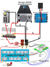
I recently purchased a 2000watt Renogy inverter/charger. Long story short it was working at first, now its not. I went on to purchase the same inverter thinking the original one had broke: https://www.renogy.com/2000w-12v-pure-sine-wave-inverter-charger-w-lcd-display/
I now have 2 and they both don't work with my setup. I have this 1200watt Giandel inverter I tried to use in the Renogy inverters place with the same falling results. Is there something wrong with my setup? I've checked all fuses, wires and came back with nothing. The DC side of my system still works fine. I have a feeling it may be something in my DC system causing the issue (maybe a neural thinks its ground or something). Any insight on how to diagnose this issue would be greatly appreciated. Thank you
See attached photo
Attachments
Last edited: