diy solar

diy solar

Wiring Diagram: How did I do?

gcp

Going nomadic.
Joined
Sep 1, 2021
Messages
49
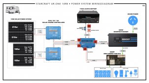
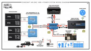
Hi! I bought my first camper and intend to do some off the grid camping with it. Other than working on my car, I knew very little about electrical systems before this. I've been doing a bunch of research and wanted to see how far it got me in terms of planning out my own system. Today I took a first stab at a wiring diagram to see if it's coming together, and if I actually understand what I'm doing. How am I doing so far? I don't know what fuses I need for my distributor yet. And I might need some in other places? I don't know if I actually need bus bars for my dual SCCs. I don't really understand how the Inverter/Charger works with the camper's existing power system yet. Feedback and guidance very much welcome and appreciated! Thank you :)

Power System Wiring Diagram v1.jpg.001.jpeg
 

Attachments

  • Power System Wiring Diagram v1.pdf
    15.4 MB · Views: 20
  • Rooftop Plan - Solar.pdf
    1.5 MB · Views: 6
  • NPA160S-12H.pdf
    394.7 KB · Views: 7
  • NPA210S-12H.pdf
    393.1 KB · Views: 3
Hi! I bought my first camper and intend to do some off the grid camping with it. Other than working on my car, I knew very little about electrical systems before this. I've been doing a bunch of research and wanted to see how far it got me in terms of planning out my own system. Today I took a first stab at a wiring diagram to see if it's coming together, and if I actually understand what I'm doing. How am I doing so far? I don't know what fuses I need for my distributor yet. And I might need some in other places? I don't know if I actually need bus bars for my dual SCCs. I don't really understand how the Inverter/Charger works with the camper's existing power system yet. Feedback and guidance very much welcome and appreciated! Thank you :)
View attachment 62615

There are 5 components to connect to a lynx with 4 fused positions.

The battery should have a discrete fuse as close as possible to the positive battery terminal.
Connect the battery to the unfused left side of the lynx

The solar charge controllers, inverter/charger and dc distribution center get connected to the fused positions on the lynx.

If you didn't already buy Renogy, I caution you that their support has been lousy for quite a while now.

A 2000 watt low frequency inverter can draw more current than that battery can provide.
 
Thank you @smoothJoey!
There are 5 components to connect to a lynx with 4 fused positions.

The battery should have a discrete fuse as close as possible to the positive battery terminal.
Connect the battery to the unfused left side of the lynx

The solar charge controllers, inverter/charger and dc distribution center get connected to the fused positions on the lynx.

If you didn't already buy Renogy, I caution you that their support has been lousy for quite a while now.

A 2000 watt low frequency inverter can draw more current than that battery can provide.
This makes sense. So I can skip the busbar and take both solar charge controllers straight into the distributor. Thank you!
I did buy Renogy already... I jumped the gun before I did my research. Good advice though, thank you.
You're right - I've been thinking I should add a second battery. Best to match it to the first one I have, right?

Oh and don't forget to disable the converter in the ac/dc distribution panel.
So the Inverter/Charge negates the need for the OEM converter altogether. Very nice.

Also I don't see a shunt based battery monitor.
Okay, I was wondering about that. I see the folks who really seem to know what they're doing use an independent BMS separate from what's built into the batteries... was trying to skip things that aren't necessary (newbie me thought the built-in BMS was enough), but this is sounding more and more necessary.) Thank you! Really appreciate all your notes.
 
battery gets 2/0 awg and 300 amp fuse
inverter/charger gets 2/0 awg and 300 amp fuse
each scc gets 10 awg wire on the system side and a 20 amp fuse
For the dc distribution panel wire and fuse check the rating of the converter and report back.
 
This makes sense. So I can skip the busbar and take both solar charge controllers straight into the distributor.
Yes each scc goes to a fused position.
The batteries go to the un-fused position because they are fused at source.
Best to match it to the first one I have, right?
Yes
So the Inverter/Charge negates the need for the OEM converter altogether. Very nice.
Yes and even more, if the converter is used while the inverter is on you will get a power loop.
Okay, I was wondering about that. I see the folks who really seem to know what they're doing use an independent BMS separate from what's built into the batteries... was trying to skip things that aren't necessary (newbie me thought the built-in BMS was enough), but this is sounding more and more necessary.) Thank you! Really appreciate all your notes.
Your batteries have built in bms so you don't need another bms(battery management system) but you could use a shunt based battery monitor.
 
battery gets 2/0 awg and 300 amp fuse
inverter/charger gets 2/0 awg and 300 amp fuse
each scc gets 10 awg wire on the system side and a 20 amp fuse
For the dc distribution panel wire and fuse check the rating of the converter and report back.
Wow, thank you, this is so kind and helpful of you!

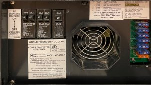
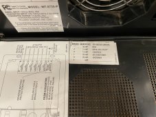
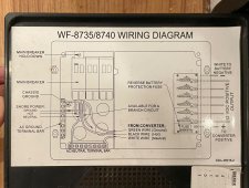
Converter is rated for accepting 105-130V, 7.5A (600W) and outputting 13V, 35A to the 12v system. Panel input is AC 12V, 30a.


IMG_0698.jpg
IMG_0700.jpeg
IMG_0699.jpg
 
Converter is rated for accepting 105-130V, 7.5A (600W) and outputting 13V, 35A to the 12v system. Panel input is AC 12V, 30a.
Hopefully the core of the system is physically close to the ac/dc distribution panel.
I say go as big as the mechanical lugs on the distribution panel allow.
Usually that is 6 awg.
Pair with a 100 amp fuse.
 
The fridge gets ac and dc power.
Never occurred to me to wonder... how does that work?
Does it use both or is there automatic precedence or is it manual configured or other?
 
Okay, I was wondering about that. I see the folks who really seem to know what they're doing use an independent BMS separate from what's built into the batteries... was trying to skip things that aren't necessary (newbie me thought the built-in BMS was enough), but this is sounding more and more necessary.) Thank you! Really appreciate all your notes.
The ammeter on my BMS gives me a rough guess + or - about 20%. I have THIS AMAZON SHUNT, its under $20, and it matches up to about 1/10th of an amp of my calibrated Fluke. I spent $100 on a Renogy battery monitor, and the cheap one is MUCH more accurate.

Its really nice to be able to see real-time voltage, current, and cumulative totals on a separate screen. For me, it's a pain in the butt to pull my phone out every time I want to see my battery's status.
 
  • Like
Reactions: gcp
The fridge gets ac and dc power.
Never occurred to me to wonder... how does that work?
Does it use both or is there automatic precedence or is it manual configured or other?
Good question. The fridge has a dial to select its power source: AC, DC, or Propane. The fridge is plugged into the AC system through its own outlet buried behind the fridge, and somewhere it is also tapped into the DC system, though I haven't see that with my own eyes yet. That's all I know about it so far.
 
Hopefully the core of the system is physically close to the ac/dc distribution panel.
I say go as big as the mechanical lugs on the distribution panel allow.
Usually that is 6 awg.
Pair with a 100 amp fuse.
Depends on what you consider to be close in the context of a 14ft camper. The OEM fuse box is located under the kitchen counter where there is no space for a battery and inverter/charger etc. I estimate that I will have to run a length of wire that is somewhere between 6-10ft from the OEM fuse box to the rest of my new power system.
 
battery gets 2/0 awg and 300 amp fuse
inverter/charger gets 2/0 awg and 300 amp fuse
each scc gets 10 awg wire on the system side and a 20 amp fuse
For the dc distribution panel wire and fuse check the rating of the converter and report back.

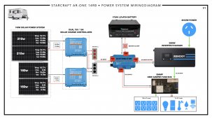
Okay, with all your excellent help, I have finished V2 of the wiring diagram.

I have questions. One practical, one out of newbie curiosity:

1. What wire gauge should I be using for the AC Output of the Inverter/Charger to the OEM Fuse Box?
2. Why does the DC In/Out of the Battery and the Inverter require such massive 00 gauge wires and 300A fuses when my camper's fuse box isn't able to draw that kind of power, and really, from my limited knowledge, not even a house connected to commercial power gets wired with such high gauge wiring and breakers/fuses.

Sending big thanks for all your help today. ?

Power System Wiring Diagram v2.jpg
 

Attachments

  • Power System Wiring Diagram v2.pdf
    16.6 MB · Views: 4
The ammeter on my BMS gives me a rough guess + or - about 20%. I have THIS AMAZON SHUNT, its under $20, and it matches up to about 1/10th of an amp of my calibrated Fluke. I spent $100 on a Renogy battery monitor, and the cheap one is MUCH more accurate.

Its really nice to be able to see real-time voltage, current, and cumulative totals on a separate screen. For me, it's a pain in the butt to pull my phone out every time I want to see my battery's status.
Such a great tip, thank you @A.Justice !
 
Depends on what you consider to be close in the context of a 14ft camper. The OEM fuse box is located under the kitchen counter where there is no space for a battery and inverter/charger etc. I estimate that I will have to run a length of wire that is somewhere between 6-10ft from the OEM fuse box to the rest of my new power system.
10 feet one way is 20 feet round trip.
That is getting a bit long but is doable.
6 awg is indicated by this calculator
 
  • Like
Reactions: gcp
1. What wire gauge should I be using for the AC Output of the Inverter/Charger to the OEM Fuse Box?
10 awg so that you don't have to replace the master breaker.
The ac input from shore power should also be 10 awg.
2. Why does the DC In/Out of the Battery and the Inverter require such massive 00 gauge wires and 300A fuses when my camper's fuse box isn't able to draw that kind of power, and really, from my limited knowledge, not even a house connected to commercial power gets wired with such high gauge wiring and breakers/fuses.

Generally fuses protect wires.
Batteries are a special case where we hope that the fuse will protect the battery too.
Class t is the best battery fuse but for 12 volts systems ANL and terminal fuses are also acceptable.

The dc panel gets 6 awg because I generally like to use the biggest wire that the mechanical lugs allow.
Since you could have a 20 foot round trip it turns out that 6 awg is actually required to keep the voltage drop below 3%.

The battery wire and inverter wire are sized for the draw of the inverter.

2000 ac watts * 1.5 low frequency inverter factor / 12 volts low cutoff = 250 service amps
250 service amps / .8 fuse headroom = 312.5 fault amps

That means a 300 amp fuse and pure copper wire with insulation rated for 105C.
You want the fuse to blow before the wire insulation melts or catches fire.

250 amps is about the max that most of us design for.
If you wanted a bigger inverter I would suggest going to 24 or 48 system volts.
 
  • Like
Reactions: gcp
10 awg so that you don't have to replace the master breaker.
The ac input from shore power should also be 10 awg.


Generally fuses protect wires.
Batteries are a special case where we hope that the fuse will protect the battery too.
Class t is the best battery fuse but for 12 volts systems ANL and terminal fuses are also acceptable.

The dc panel gets 6 awg because I generally like to use the biggest wire that the mechanical lugs allow.
Since you could have a 20 foot round trip it turns out that 6 awg is actually required to keep the voltage drop below 3%.

The battery wire and inverter wire are sized for the draw of the inverter.

2000 ac watts * 1.5 low frequency inverter factor / 12 volts low cutoff = 250 service amps
250 service amps / .8 fuse headroom = 312.5 fault amps

That means a 300 amp fuse and pure copper wire with insulation rated for 105C.
You want the fuse to blow before the wire insulation melts or catches fire.

250 amps is about the max that most of us design for.
If you wanted a bigger inverter I would suggest going to 24 or 48 system volts.
Totally makes sense - many thanks for all your guidance! I've made all your recommended changes in V3 of the diagram. Also thanks for that great wire gauge calculator.

One thing I have not dissected on my camper yet is the 7-way-connector wiring. I'm not sure how it connects to the camper's 12v system and ebrakes. I don't see any accommodation for it in the fuse box. Doing more research on this still.

If I were going to add a DC-to-DC charger so I could use my tow vehicle's alternator to charge my battery in gloomy/dark weather, do you know where that would hook up to this system? Do I need a distributor that has more lugs?

Power System Wiring Diagram v3.001.jpeg
 

Attachments

  • Power System Wiring Diagram v3.pdf
    16.8 MB · Views: 0
One thing I have not dissected on my camper yet is the 7-way-connector wiring. I'm not sure how it connects to the camper's 12v system and ebrakes. I don't see any accommodation for it in the fuse box. Doing more research on this still.
My suggestion is to isolate the running gear including e-breaks and tow cable and leave it as a separate system.
A dc2dc charger is going to draw way more current than that tow cable can deliver anyway.
My concern with running a tow cable and a high current dc2dc in parallel is if the high current negative failed the tow cable negative would likely melt or start on fire.
I guess you could fuse both positive and negative but I have not thought this through so I can't recommend it.
Anybody else want to weigh in here?
@RF_Burns I bet you have some wisdom on this.
If I were going to add a DC-to-DC charger so I could use my tow vehicle's alternator to charge my battery in gloomy/dark weather, do you know where that would hook up to this system? Do I need a distributor that has more lugs?
These are the busbars I used in my setup.
For the negative side I just put 7 zcase fuses underneath the busbar.
Not sure if its supported but I use both mrbf and zcase fuses with these.
Gives more options for price and capacity.
Even with the 7 fuses underneath the negative busbar its a cost effective solution.
 
Back
Top