I don't see this problem at low loads on mine. I would suggest to contact the manufacturer. It might be that it goes into standby mode too quick because it thinks there is no load. Their engineers actually seem to care and should be able to help out.


You are using an out of date browser. It may not display this or other websites correctly.
You should upgrade or use an alternative browser.
You should upgrade or use an alternative browser.
WZRELB Reliable Inverters Low Voltage Cutoff Mod How To
- Thread starter heavy-impact
- Start date
I noticed the light blinking when I first bought it. Months later now, I have it connected to a transfer switch and when I tested yesterday this issue is causing the lights to flicker. I can video the output end of the panel and I bet they will know exactly what is wrong. I had pretty much decided that would be my next move. Thanks for the input.I don't see this problem at low loads on mine. I would suggest to contact the manufacturer. It might be that it goes into standby mode too quick because it thinks there is no load. Their engineers actually seem to care and should be able to help out.
I noticed the light blinking when I first bought it. Months later now, I have it connected to a transfer switch and when I tested yesterday this issue is causing the lights to flicker. I can video the output end of the panel and I bet they will know exactly what is wrong. I had pretty much decided that would be my next move. Thanks for the input.
You may have done this but step 1 is to double check ALL connections in the system.
Also be certain you are delivering adequate DC current and voltage.
Just a couple thoughts.
No Load (video)
10watt LED (video)
60watt load (video)
At some larger load point (have not taken the time to zero in on the value) the problem goes away.
Just by the looks of it, it would be something like some voltage (internally) gets too high and some circuit control cuts output until the voltage is back down, then the voltage builds again, and the cycle repeats. Under enough load the offending circuit point is loaded enough that the voltage can't out of the limit, so the problem is not then seen.
Connections and available power are good. Inverter fed directly from battery terminals (2 in parallel with separate cables), no BMS, no possible weak point between battery and inverter.
Last edited:
RCinFLA
Solar Wizard
- Joined
- Jun 21, 2020
- Messages
- 3,563
Having a fixed LBCO can be a problem. One thing common to many setups is too much resistance voltage drop in the battery lines, primarily due to too small gauge cable for current used during peak load.
You would like to have the inverter hit LBCO before BMS low cell shutoff but with too much cabling voltage drop on heavy loads you have a hard time setting inverter LBCO high enough and not have inverter spurious shut downs on heavy load. Some inverters have an adjustable LBCO timer that helps for surge loads by requiring the LBCO voltage to stay below trip voltage for some set time. A real low battery condition is slow and sustained, a surge load induced voltage drop on inverter can be ignored with a LBCO timer to ride over the short time period of inverter input voltage sag.
Nothing to do with LBCO, but many of the low cost Chinese inverters have trouble with PWM output AC filter. Biggest issue is the toroid cores are not physically large enough to handle high 50Hz or 60 Hz AC current without saturating the core. The low freq AC is like a heavy DC bias on the core forcing it near magnetic saturation where the inductance drops to low level. When this happens there is no longer sufficient high frequency PWM filtering. They skimp on inductance to avoid severe core saturation for the smaller core but this creates a lower reactive load during light loading on inverter raising DC idle current draw.
Last edited:
theoldwizard1
New Member
- Joined
- Jul 17, 2020
- Messages
- 77
Most low cost Chinese inverter use a "high frequency" front end. The incoming DC is pulsed and sent to multiple EI core transformers. The output of these transformers is rectified using Schottky diode resulting in high voltage DC. This is converted input a high voltage AC output typically using an EGS002 daughter board (based on a EG8010), some MOSFET drivers (IR2110 or similar) and then a number of power MOSFETs. The typical putput filter is just an L and a C.Nothing to do with LBCO, but many of the low cost Chinese inverters have trouble with PWM output AC filter. Biggest issue is the toroid cores are not physically large enough to handle high 50Hz or 60 Hz AC current without saturating the core.
More "expensive" designs use low voltage, high current to drive a large toroidal transformer.
Some of the Chinese companies are now using PIC based controllers instead of the the EG8010. Similar functionality but there is much more flexibility in feedback and output to drive user interfaces.
Here is an update. The MFG replied to my support request. "The problem happens most often when the battery voltage is high and the load is light". It appears the inverter is shutting off and on several times per second because the high voltage DC is too high. I was asked to drop the battery voltage to 24.0v and test. Everything was fine at 24.0v. At 24.3, you could see a flicker in a 60w incandescent lamp. I am using LiFePo4 batteries so 24.0v is a bit of a joke. I have not heard back from them if there is an option to adjust it or not.
Another note, at 26v when the load gets to about 1400 watts the flickering in the lights stops.
Another note, at 26v when the load gets to about 1400 watts the flickering in the lights stops.
Interesting. Mine is a 48V version - I got to go try and replicate what you see.
With the inverter on and no load, the red light on the inverter is pulsing like a heartbeat. Lighting loads, the lights pulse in sync with the red light. More load, the light goes faster until you can't see it any longer. But you can see the lights pulsing.Interesting. Mine is a 48V version - I got to go try and replicate what you see.
I just quickly tested. My battery sits at 53V. I both connected a single small load and also ran no-load. I don't have the red LED come on at all, and everything works fine.
Up in smoke
New Member
- Joined
- Feb 9, 2021
- Messages
- 1
Didn't work on my 2000 watts, my voltage regulation board is different than yours or I'm on the wrong board! My R11 resistor was 10k (1002).If you have one of these off grid inverters and the low voltage cutoff activates out of spec or you just want to adjust the low voltage cutoff lower or higher you can do this mod. You will need a few inches of 30 gauge wire and a 10K trimmer pot, (I like the 15 turn ones) and a soldering iron with small tip. It helps to have a magnifying visor and a hot glue gun.
Disconnect the inverter from any power.
Remove the cover from the inverter.
Locate the voltage regulation board just in front of the short heat sink.
Remove the R11 resistor with a soldering iron and tweezers.
Solder a couple inches of wire onto the center leg and either outer leg of the trimmer pot. Doesn't matter which outside leg just use one or the other.
Connect a ohm meter to the trimmer center leg and whichever outside leg you plan to use and set the trimmer to 5000ohm.
Solder the two wires from the trimmer pot to the R11 solder pads where you removed the resistor.
If you have a benchtop power supply you can power the inverter from it to set the low voltage cutoff using the trimmer, otherwise set it with a low battery.
Lower the trimmer resistance to lower cutoff voltage. Increase resistance to raise the cutoff voltage.
I put hot glue over my alarm because I hate it and don't need it.
If you're not comfortable doing this type work then pay someone else to do it.
View attachment 24832View attachment 24833View attachment 24834

Hello all. I’m new here but I’m hoping someone can help me out.
So I did this mod with the intent of turning the voltage cutoff to the mid 9’s (I have a 12v 1000w 120v) but alas - this is unfortunately when I realized my soldering skills aren’t nearly what they used to be in my older age.
I damaged the pad of the resistor and then when tried to repair it damaged a trace and probably the LM224 ic along with it. It actually DID work perfectly. Once. Then nothing so I am assuming the voltage control board is damaged beyond repair.
Problem is - apart from waiting for the manufacturer to get back to me then slowly ship me one from China (which could take months) I can not find this exact board anywhere at all. And believe me I’ve looked. Everywhere
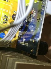
Can anyone tell me where I can get a replacement board or compatible one?? The ones I’ve found don’t have the on off switch input nor the horn (not that I need that). Only thing written on the board other than the ic part numbers is “LBQJ - v4.2”
I have the same one pictured in the original post. Can anyone please help??? Thanks I’m advance.
So I did this mod with the intent of turning the voltage cutoff to the mid 9’s (I have a 12v 1000w 120v) but alas - this is unfortunately when I realized my soldering skills aren’t nearly what they used to be in my older age.
I damaged the pad of the resistor and then when tried to repair it damaged a trace and probably the LM224 ic along with it. It actually DID work perfectly. Once. Then nothing so I am assuming the voltage control board is damaged beyond repair.
Problem is - apart from waiting for the manufacturer to get back to me then slowly ship me one from China (which could take months) I can not find this exact board anywhere at all. And believe me I’ve looked. Everywhere
Can anyone tell me where I can get a replacement board or compatible one?? The ones I’ve found don’t have the on off switch input nor the horn (not that I need that). Only thing written on the board other than the ic part numbers is “LBQJ - v4.2”
I have the same one pictured in the original post. Can anyone please help??? Thanks I’m advance.
Attachments
Last edited:
I damaged the pad of the resistor and then when tried to repair it damaged a trace and probably the LM224 ic along with it.
Unless you overheated the LM224 it should be fine. Fixing the trace with some wire should be worth a try. Even if that LM is broken, it's a €0.42 part or so, so you could replace that too.
If you're in Europe somewhere I could give a go at fixing it.
I don't know of any other source besides the manufacturer.
I did indeed overheat and damage the LM224 when I tried to repair it. Unfortunately I hadn’t realized how much the disease I have has progressed until I tried to do some precise soldering and couldn’t stop my hands from shaking. It just started getting worse the more I tried because I got frustrated. I should have walked away for the night.
Also unfortunately I’m in the United States but I do appreciate the offer.
If all else fails I’m sure the MFG can send me a new board - and worst worst case scenario I will try to get a new LM224 and be more careful repairing it. Was just hoping someone would know where to get one besides the MFG, or if there was a compatible one.
heavy-impact
New Member
- Joined
- Apr 28, 2020
- Messages
- 71
You can purchase a new LM224 op amp if need be and bypass the bad section of trace by soldering a piece of wire from one solder point to the next. If your hands aren't steady enough take all the parts to an electronics repair shop or TV repair shop and point out what you want soldered.
Good luck.
Good luck.
I just removed the r11 resistor based on this thread. After removal, the inverter stopped working - when i turn it on it just runs the alarm directly. Perhaps i should connect the 2 Solder lugs left after the resistor? Or what am i getting wrong?No, the cutoff will continue working at about 2.5v less than the factory setting.
RCinFLA
Solar Wizard
- Joined
- Jun 21, 2020
- Messages
- 3,563
Can't believe they told you this. A real poor inverter design. They appearently have an voltage overshoot ringing problem on the DC-HV DC converter first stage that is tripping its momentary shutdown. Then it takes some time to recover causing a momentary slump in DC high voltage to run the output PWM sinewave chopper. Great for surge current on input DC-HV DC converter MOSFET's putting extra stress on them.Here is an update. The MFG replied to my support request. "The problem happens most often when the battery voltage is high and the load is light". It appears the inverter is shutting off and on several times per second because the high voltage DC is too high. I was asked to drop the battery voltage to 24.0v and test. Everything was fine at 24.0v. At 24.3, you could see a flicker in a 60w incandescent lamp. I am using LiFePo4 batteries so 24.0v is a bit of a joke. I have not heard back from them if there is an option to adjust it or not.
Another note, at 26v when the load gets to about 1400 watts the flickering in the lights stops.
Last edited:
RCinFLA
Solar Wizard
- Joined
- Jun 21, 2020
- Messages
- 3,563
Low cost high frequency hybrid inverters will do this because their DC to HV DC converter first stage has to make a power flow mode change if it is in charging battery. When charging, and it detects an input AC loss it will reverse its DC-HV DC converter direction to supply inverter output power from batteries. This takes a little bit of time which will cause the glitch when transfer switch flips.I noticed the light blinking when I first bought it. Months later now, I have it connected to a transfer switch and when I tested yesterday this issue is causing the lights to flicker. I can video the output end of the panel and I bet they will know exactly what is wrong. I had pretty much decided that would be my next move. Thanks for the input.
Once the transfer switch completes and AC input is applied again it must synchronize to new AC source, which can take a few of seconds, and go back through the DC-HV DC converter reversal process again before returning to battery charging. This means there will a few seconds of interruption in charging. This may also cause a second glitch in output AC depending on how much AC output load is when DC-HV DC converter makes its flow direction change again .
LF hybrid inverters can make the battery power flow direction change instantly.
Hello i will try to write more about my problem with this type of inverter. Maybe Somebody can help...
So i have the 1000w version in my camper And the problem is that lately when my 230v fridge starts running the commpressor sometimes there Is a slight voltage drop And the inverter starts beeping or even cutoffs the voltage even when the batteries Are almost full.
I found this thread based on which i would like to make the cutoff voltage as low as possible or even turn off this function completely. I have lifepo batteries with bms So i really dont need IT anyway.
So i Went ahead And desoldered the r11 resistor. After that when i Turned one the inverter IT just gives me a continous beep and never starts running. Maybe the problem is i did not add the trimmer and therefor left the Circuit open. Perhaps if i just take a piece of wire and make a connection between the two Solder lugs where the r11 resistor was to close the Circuit, Will IT fix my problem? Or can i just unplug the White wire connected to the voltage cutoff board to completely bypass it? Thanks for any input.
Since i live in the camper And really need the inverter working i dont want to make a Mistake And have no power but having IT beep every night Is also super annoying!
RCinFLA
Solar Wizard
- Joined
- Jun 21, 2020
- Messages
- 3,563
You really do not want BMS to disconnect battery as the primary low voltage detection. There are several potential issues doing this, relating to surge currents on restart. If you have a battery monitor for AH tracking you may also lose the cumulative AH info.I found this thread based on which i would like to make the cutoff voltage as low as possible or even turn off this function completely. I have lifepo batteries with bms So i really dont need IT anyway.
If you have an adjustable inverter low battery cuttoff, and you are unable to get an acceptable low battery inverter shutdown, it is usually caused by too much battery cable voltage drop on peak current demand (too small battery line wire gauge) or insuffcient battery size to support peak current demand.
With LFP batteries with a low cost BMS, the BMS MOSFET series switch resistance also comes into play during peak surge current voltage slump. Their switch resistance relates to their max current rating. Many of the low cost BMS current ratings are based on their peak current capability before they self destruct and should not be used with a continuous current greater than about half their specified current rating. They have an overtemp shutdown but that does nothing for surge current voltage drop across the BMS.
If inverter has a low battery voltage trip delay timer adjustment setting, it can be used to ignore momentary peak current DC input voltage slump.
If you allow batteries to get significantly out of balance it can impact on how low battery detect reacts. You will get significantly less capacity for battery array so original battery monitor AH capacity setting will likely be far off. When cells get to less then 20% state of charge their voltage slump under heavy load current will be greater, particularly if current peak last longer then 20-30 seconds.
Last edited:
Similar threads
- Replies
- 1
- Views
- 195
- Replies
- 4
- Views
- 347
- Replies
- 9
- Views
- 2K
- Replies
- 37
- Views
- 2K