


You are using an out of date browser. It may not display this or other websites correctly.
You should upgrade or use an alternative browser.
You should upgrade or use an alternative browser.
Inverters High or Low Frequency ?
- Thread starter Noel
- Start date
Steve_S
Offgrid Cabineer, N.E. Ontario, Canada
Covers it very well.
 www.magnum-dimensions.com
Inversion Methods Explained: High Frequency vs Low Frequency | Magnum Dimensions
Understand the difference between high frequency and low frequency inverters with this quick article.
Couple threads to get you started:

 diysolarforum.com
diysolarforum.com
diysolarforum.com
Low Frequency Inverters
A handful of people around here recommend low frequency inverters, I wasn't aware of the distinction before joining this forum, and most companies don't seem to push this as a marketing point and most reviews don't mention it. And I've found very few clearly marked low frequency inverters at the...
diysolarforum.com
Inverters with remote wire
Considering using electrodacus bms. However the inverter I planned to used giandel 24v 2000 wat has a momentary switch to it. The one electrodacus recommends is "slightly higher in price" at 3 times the price lol
diysolarforum.com
D
Deleted member 1888
Guest
How do you tell a HF from a LF?
D
Deleted member 1888
Guest
Also do they have 12v and 24v Low Frequency inverters?
How do you tell a HF from a LF?
Read the threads I linked to above (and the links in those threads), then circle back if you still have questions.
Short answer: LF = Bigger, heavier, more expensive, higher and longer surge rating, frequently but not always inverter/charger combos.
Also do they have 12v and 24v Low Frequency inverters?
Yes
What is low frequency? What is high frequency?
Guys and gals, please take a minute or two to click through and read the links already posted by @Steve_S and myself before asking general questions that are already answered there. If something is still unclear or you have specific questions, then ask.
Personally I felt there was a good amount of info in the article Steve linked to. The company that wrote the article is a respected company and sells both LF and HF inverters.
---------------------------------------------------------------------
IRON CORE TRANSFORMERS AND FIELD EFFECT TRANSISTORS
There are two distinct types of industrial grade power inverters distinguished by the size of their transformers, and the switching speed of their transistors. The ability of an inverter to absorb the electrical surges inherent in certain loads like motors, pumps, and torque-related tools is directly proportional to the physical amount of iron present in the transformer. Size and tolerances of the transistors used in the inversion process, and the speed at which they operate determines the classification of high or low frequency.
INVERSION METHODS EXPLAINED
High Frequency Inverters (HF)
The large majority of inverters available in the retail market are high frequency. They are typically less expensive, have smaller footprints, and have a lower tolerance for industrial loads. HF inverters have over twice the number of components and use multiple, smaller transformers. Their application is appropriate for a wide variety of uses like tool battery chargers, small appliances, A/V and computers, but have a decreased capacity for long term exposure to high surge loads like pumps, motors, and some high-torque tools.
Low Frequency Inverters (LF)
Our UL-listed, low frequency inverters and inverter/chargers are the pinnacle of electrical durability. The massive iron core transformer is aptly capable of absorbing surge loads because of the “Flywheel Effect” inherent in the physical amount of a transformer’s iron. LF inverters have larger and more robust Field Effect Transistors (FET’s) that can operate cooler, in part due to the slower frequency of switching required to produce AC power. These inverters are feature rich to include the optional ability to hardwire additional external GFCI outlets, input of multiple DC voltages, provide regulated dual output voltages (120/240VAC), and integrate chemistry appropriate battery chargers and transfer relays for shore power.
HIGH FREQUENCY
Pros
Pros
---------------------------------------------------------------------
blue text = [my additions] andsubtractions
*My additions are based on info from this thread which was linked to in my previous post, some additional info can be found in this post which has also already been linked to. My subtractions were the only parts of the article that seemed like 'pure marketing'
---------------------------------------------------------------------
IRON CORE TRANSFORMERS AND FIELD EFFECT TRANSISTORS
There are two distinct types of industrial grade power inverters distinguished by the size of their transformers, and the switching speed of their transistors. The ability of an inverter to absorb the electrical surges inherent in certain loads like motors, pumps, and torque-related tools is directly proportional to the physical amount of iron present in the transformer. Size and tolerances of the transistors used in the inversion process, and the speed at which they operate determines the classification of high or low frequency.
INVERSION METHODS EXPLAINED
High Frequency Inverters (HF)
The large majority of inverters available in the retail market are high frequency. They are typically less expensive, have smaller footprints, and have a lower tolerance for industrial loads. HF inverters have over twice the number of components and use multiple, smaller transformers. Their application is appropriate for a wide variety of uses like tool battery chargers, small appliances, A/V and computers, but have a decreased capacity for long term exposure to high surge loads like pumps, motors, and some high-torque tools.
Low Frequency Inverters (LF)
HIGH FREQUENCY
Pros
- Smaller footprint
- Less expensive
- [often marginally more efficient with lower idle power consumption]
- Doesn’t operate well with high-surge loads like pumps and high-torque tools
Pros
- Runs well with high-surge loads
- Operates cooler
- [reputation for being more durable/reliable/long lasting]
- Heavier [and larger]
- More expensive
---------------------------------------------------------------------
blue text = [my additions] and
*My additions are based on info from this thread which was linked to in my previous post, some additional info can be found in this post which has also already been linked to. My subtractions were the only parts of the article that seemed like 'pure marketing'
I am an EE and design DC-DC switching power supplies. I have used and am aware of how industrial VFD motor drives are designed and work.
VFD drives typically use switching frequencies around 4KHz, but also typically have terrible harmonic content (noise) in their output. Basically they are useless for pretty much anything but driving motors and then only really useable in an industrial setting.
DC-DC switching regulators normally use much higher switching frequency 100KHz up to 2MHz. The higher the frequency is, the smaller, lighter and less expensive the magnetics can be.
The vendor specifically referred to high and low frequency as being important without explaining "how or why" what they are doing is better. They didn't even define what they mean by "high" and what they mean by "low".
Low frequency in AC power could mean 60 Hz, which I seriously doubt since that would require an incredibly inefficient system to output low harmonic content "true" sine wave power.
Last edited:
I am an EE and design DC-DC switching power supplies
I feel like after a bit of research you will probably have some good input/info to contribute to the conversation.
The vendor specifically referred to high and low frequency as being important without explaining "how or why" what they are doing is better.
I'm not seeing where they say anything to that effect. But its not really important here anyways, if the topic is HF and LF, no need to get sidetracked with Magnums marketing pitch. They make both HF and LF inverters so I see no reason to distrust the comparison.
They didn't even define what they mean by "high" and what they mean by "low".
I feel like they did an okay high level job differentiating the two here, though I can see how it lacks specificity and details.
There are two distinct types of industrial grade power inverters distinguished by the size of their transformers, and the switching speed of their transistors. The ability of an inverter to absorb the electrical surges inherent in certain loads like motors, pumps, and torque-related tools is directly proportional to the physical amount of iron present in the transformer. Size and tolerances of the transistors used in the inversion process, and the speed at which they operate determines the classification of high or low frequency.
I think the purpose of that article is a high level overview for customers/potential owners, and I think it does a decent job at that (articulating why you would choose one over the other, and the basic differences). For a more in depth explanation I'm not sure where to look, but if you find out more, please report back here or in the thread I linked to, so we can all learn a bit.
Haven't watched this video yet, but you might find some of what you are looking for here:
Thanks. I am asking for technical details so I can determine if there is something to this claim because it differs from my understanding.
I am interested in the subject, I design similar kinds of devices, but not specifically DC to AC power inverters. In general, for power electronics higher frequencies typically result in more efficient and lower cost products.
I would like to understand why lower frequency inverters are perceived to be more robust. At first impression it is sounding like old is better than new bias. This can be accurate, an older, well designed device with lots of margin will be much more reliable than a value engineered new device that is operating on the edge of failure. But that doesn't mean that a properly implemented modern design is inferior to older products. The reverse is normally the case.
Thanks. I am asking for technical details so I can determine if there is something to this claim because it differs from my understanding.
I am interested in the subject, I design similar kinds of devices, but not specifically DC to AC power inverters. In general, for power electronics higher frequencies typically result in more efficient and lower cost products.
Just to be clear (you may already know this), this is not the claim of a single company, Samlex, Magnum, Victron, and others all make Low Frequency inverters, I believe all these companies also make high frequency inverters as well.
I would like to understand why lower frequency inverters are perceived to be more robust. At first impression it is sounding like old is better than new bias. This can be accurate, an older, well designed device with lots of margin will be much more reliable than a value engineered new device that is operating on the edge of failure. But that doesn't mean that a properly implemented modern design is inferior to older products. The reverse is normally the case.
I suppose there is probably a bit of the old > new thing going on, but I also have the impression that there are some very real differences, most notably surge rating (in terms of power and duration) and I imagine there is a reason that many reputable companies top of the line large inverters have remained LF even while the same companies smaller and low-mid range inverters have transitioned to HF.
You may also want to look into 'hybrid' HF inverters, some companies (Victron comes to mind) are advertising 'hybrid' HF which they claim can handle high startup loads, but keeps the efficiency of HF. Might be marketing BS, might be legit (it is worth noting Victron has some of the highest efficiency inverters), there buzzword for it is 'SinusMax'.
I look forward to hearing what you learn, since a lot of this is a bit over my head.
Okay, after a good bit of googling I may have found a resource that will appeal to you:
A Review of Inverter Design and Topologies -- Trace Engineering
Also a bit of a fuller explanation (still probably less detailed than you would like) here:
A Review of Inverter Design and Topologies -- Trace Engineering
Also a bit of a fuller explanation (still probably less detailed than you would like) here:
Low-frequency inverters use high-speed switches to invert (or change) the DC to AC, but drive these switches at the same frequency as the AC sine wave which is 60 Hz (60 times per second). This requires the inverter’s transformer to work a bit harder, plus demands it to be larger and heavier, thus the result is a bigger, beefier package. High-frequency models typically drive the switches at a frequency closer to 50 KHz (50,000 times per second) or higher, thus allowing for a smaller, more efficient transformer and overall smaller package. However, that efficiency comes with a price. High-frequency inverters typically surge at a lower rate, or for shorter periods of time than its low-frequency counterparts.
I will do some research. My initial reaction was BS, but that is not based on specific knowledge. I will let you know what I learn.
Both the HF and LF inverters operate at 60Hz in the US so I think that may be part of the misunderstanding.
In your research you will find that the LF inverters weigh about twice as much as the HF ones. Both pure sine wave.
The weight is due to a huge transformer which can allow the LF units to handle large surges. In some cases up to 3X rated power for up to 20 seconds while a HF one is typically rated for 2X surge for some amount of milliseconds.
Hope that helps.
First off...I am an EE and design DC-DC switching power supplies. I have used and am aware of how industrial VFD motor drives are designed and work.
VFD drives typically use switching frequencies around 4KHz, but also typically have terrible harmonic content (noise) in their output. Basically they are useless for pretty much anything but driving motors and then only really useable in an industrial setting.
DC-DC switching regulators normally use much higher switching frequency 100KHz up to 2MHz. The higher the frequency is, the smaller, lighter and less expensive the magnetics can be.
The vendor specifically referred to high and low frequency as being important without explaining "how or why" what they are doing is better. They didn't even define what they mean by "high" and what they mean by "low".
Low frequency in AC power could mean 60 Hz, which I seriously doubt since that would require an incredibly inefficient system to output low harmonic content "true" sine wave power.
HF, and LF in relation to household inverters has nothing todo with the AC frequency. That is fixed by the country and usage needs of the consumer... and devices.
the terms are a product differential spec... basically between the surge abilities... HF equals nanosecond surge... LF equals SECONDS of surge...
Okay, after a good bit of googling I may have found a resource that will appeal to you:
A Review of Inverter Design and Topologies -- Trace Engineering
Also a bit of a fuller explanation (still probably less detailed than you would like) here:
Thanks that answered my questions. No surprises there.
F.Y.I. There are essentially 3 kinds of inverter outputs.
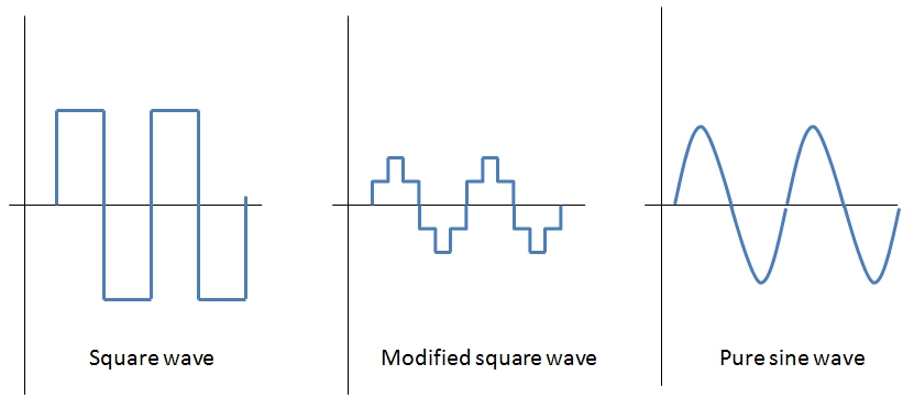
Square wave. This is the cheapest and is the noisiest electrically . Switching happens at line frequency (60 Hz). There is some kind of low pass filtering on the output, but this is only really good for running electrical motors and they are going to run hotter than normal. Running electronics from one of these would be a bad idea. Square edges contain a huge quantity of higher frequencies at odd octaves (3rd, 5th, 7th... octaves). This is what is called harmonic noise. Square wave inverters originated in older mechanical inverters that used mechanical switches to create the square wave output.
Modified square wave . This is essentially a very poor mans version of a sine wave. Switching frequency is at three times line frequency (180 Hz) and is again full of harmonic noise. Not as bad as a square wave output, but still nothing to run sensitive electronics from. Makes motors and stuff happier.
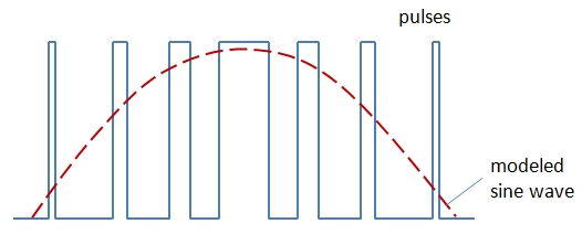
"Pure" sine wave. This is actually generated using square waves switching at much higher frequency than line frequency. The duty cycle of the square wave is adjusted on the fly to create an reasonable approximation of a sine wave. The higher the switching frequency, the smoother the approximation of a sine wave is and the easier it is to filter out harmonic noise (which is the expensive part). This is what modern inverter designs use. A Class D audio amp works in a similar fashion if that comparison helps.
The low frequency inverters discussed in previous threads use a ferro-resonant transformer to low pass filter a square wave output switching at 60 Hz. I am familiar with ferroresonant transformers having used them in industrial applications since the 80's. In particular I spec'ed Sola MCR power conditioners as part of any process control system I worked on back in the 90's when that was my day job.
Sola/Hevi-Duty Products | Sola MCR Hardwired Series Power Conditioners
The Sola MCR Hardwired Series provides excellent noise filtering and surge suppression to protect connected equipment from damage, degradation or misoperation. Combined with the excellent voltage regulation inherent to Sola/Hevi-Duty's patented ferroresonant design, the MCR can increase the...
solahevidutysales.com
An MCR/CVS does a decent job of cleaning up line noise and provides some AC line regulation as well, but they are large, heavy, expensive and have a limited load dynamic range. These are normally only used in applications where the load doesn't change since they will overheat if lightly loaded (below 20% of capacity). Typically you size them so the load is between 40 to 70% of the rated capacity of the MCR/CVS. These are noisy too (acoustically).
I have a hard time understanding why a ferro-resonant transformer would be considered a great choice in an inverter application when the possibility exists that there might not be a load connected to the inverter. I have seen CVS regulators burn up when run with the load disconnected. I guess a smart inverter could detect the fact there is no load and shut down to protect the transformer, but then you wouldn't have a power output. The efficiency of one of these would not be great either.
Incidentally large variable speed motor controls (called VFD's) are used to run extremely large motors rated in the hundreds and thousands of horsepower. These VFD drives use a version of the "Pure" sine wave drive concept. These change the output frequency to control the rotary speed of synchronous AC motors. VFD circuitry has been refined greatly over the last 40 years and is both extremely reliable and inexpensive. This is the same electronics that make electric cars possible.
I can't imagine that modern inverters wouldn't use the same power switching circuitry as VFD's. I can also think of no reason to use 80's technology instead. I can believe that a $200 inverter from China could be crap, but that is because they have shaved every penny out of the design, not because it uses a modern switching topography.
P.S. Modern switching systems can be designed to handle huge surge currents. You should see what kind of demands an electric motor makes on the VFD drive when operating a dynamic load. 10x surge currents are not unusual.
Last edited:
Similar threads
- Replies
- 103
- Views
- 3K
- Replies
- 3
- Views
- 239
- Replies
- 3
- Views
- 357