I’d be curious to see the inrush current trace of that inverter - i’ve never bothered with precharge for 12V inverters.
Thanks for looking at the setup.
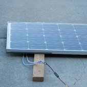
My goal was to just show a proof of concept for people to see how a solar panel can be used to pre-charge "any" inverter and potentially simplify the process vs adding in resistors and other circuits.
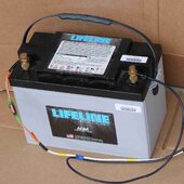
That one AGM battery will power up any inverter that I have ever attached to it just fine. The main reason to pre-charge in general is to protect the BMS from tripping in Li batteries, at least in my mind. I have most definitely seen that happen on a Victron 3000 / 12 with 3 Li batteries in parallel. It tripped just one of the battery's BMS so the system seemed to work, just not correctly.
4 of those Lifeline AGMs in series can power up a Victron quatro 5000 / 48 at my shop with no problem. 4 battleborns in the same use will trip without a pre-charge. It is easy to re-set though by turning the breaker on / off a few times to re-set the BMS. Some people don't like to do this.
_______________
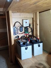
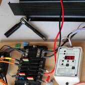
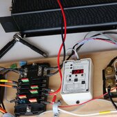
I used components that I had sitting around so that is why it is built from a bluesea fuse block, bogart SOC monitor and 10 awg wire. The limitation is that this means that the max fuse size rating is 30 amps, and I have a 30 amp in line fuse at the battery, and then 30 amp fuses in the fuse block locations for power coming in, and at the location feeding the inverter. So quite a bit less than you would normally have for a 1000 watt / 12 volt inverter.
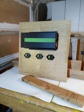
The bogart monitor tracks voltage, current and then turns this into SOC, but only displays one at a time. (unless you look at the wireless display ) so my plan was to have it on the "current monitor" display and watch what happens. What really happened is that the surge when not pre-charged caused the bogart to switch what was being displayed, so it went into somewhat of a fault mode. This eliminated my ability to watch it real time - at least with this setup.
So this limited this setup to just act as a go / no go guage - "will it blow a 30 amp fuse or not as an "indicator" of the inrush current".
Without the solar panel pre-charging the inverter - the 30 amp fuse blew instantly.
With the solar panel pre-charge - it didn't.
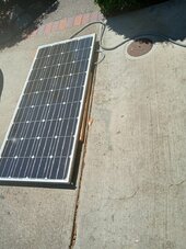
This panel is a nominal 18 volt Vmp panel, but it could also be used to pre-charge a 24 volt system. For higher voltage packs, a different panel can be used that more closely matches that need. The size / power output of the panel does not matter either as it is just to trickle it in there.


")