diy solar

diy solar

Do I need diodes in this battery design?

moonlight23

New Member
Joined
Aug 8, 2022
Messages
47
I’m building a portable battery power station and I want to use a MPPT charge controller to charge the battery from solar AND AC power from the wall. Both will be connected to the PV input on the MPPT.

Will there be issues with current backflow from solar panels to the PSU, or from the PSU to panels? If so, would some diodes (yellow boxes) prevent this? What diode value would I need?

PSU is a Meanwell LOP-600-36 (16A, 36v) and the MPPT is a Victron 100/15 (15A, 100V).
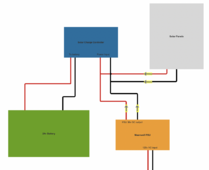
Screenshot 2024-05-02 at 3.03.03 PM.png
 
I do not understand, why wouldn't you just connect a regular charger to the battery?

This seems to me like making poor compromises for no reason or because you already have part of the equipment like PSU?
 
Why not just use a 24V charger like NPB-360-24
I do not understand, why wouldn't you just connect a regular charger to the battery?

This seems to me like making poor compromises for no reason or because you already have part of the equipment like PSU?

I want this all contained in a case where I just plug in a cable into the case, that's connected to the PSU input. Dedicated chargers are too large to shove in the case, even the Meanwell NPB-360-24.

I'd later also have the PSU 36v output connected to outer terminals if I never need 36v DC for whatever reason.
 
or a LOP-600-27

That has adjustable voltage of 25.6-28.4V

How would this 27v PSU work for this situation? Wouldn't it not float-charge once the batter is almost full? I don't want to manually monitor the charging and disconnect when required. I'd rather just let the MPPT not pull anymore power when the batter is full. Let me know if I'm missing something.
 
You would need a blocking diode rated for Isc on the solar panels. You might or might not need a blocking diode for the power supply, I’d put one in anyway.

 
^ Thank you, that's very helpful!

And just to clarify, I would never be charging the battery from solar panel and wall AC at the same time. I suppose that would make it pointless to put blocking diodes on the panels? I'll add one between the PSU to the MPPT though.
 
You watched the video, yes? You want to prevent the panels from acting like giant (IR) LEDs when the power supply applies a voltage.
 
How would this 27v PSU work for this situation? Wouldn't it not float-charge once the batter is almost full? I don't want to manually monitor the charging and disconnect when required. I'd rather just let the MPPT not pull anymore power when the batter is full. Let me know if I'm missing something.

If this is LFP, you could simply set it for 27.2V and it would fully charge it. that's not an ideal float voltage, but it works.
 
MPPT charge controller to charge the battery from solar AND AC power
Use a battery charger connected to the battery.

The Meanwell type of power supply do not have an ideal current limit, they fold back or burn out if overloaded.

Connecting to the MPPT input via a diode, (only needed in the positive path of each source), may work, ( use a 35A bridge rectifier on heat sink, inputs to each ac tab, output from + tab).

A better , more eficient, safer, and correct charging, is a charger to the battery,
 
Other threads discuss using mppt to raise or lower voltage from a fixed source (battery or powersupply) to charge a battery. In short, the way an mppt works does not play well with the non-solar panel source.

Since the psu has more power than the mppt can use, it might work OK. I would put a switch to select one input or the other.
 
Last edited:
That sounds like a fun project! Every remote control on the block would stop working maybe? :)
You might have to modulate it (there’s a static IR source that probably swamps everything else) but it might be worth a try. If you know what brand of TV your neighbor has, you could probably modulate it with a volume up signal or something silly.😁
 
Last edited:
You risk frying the MPPT.

That meanwell can provide up to 25A (peak), thus exceeding the max input current of the MPPT of 15A.

Also, if you connect both panels AND the Meanwell in parallel, it will even easier exceed that 15A. Apart from that, not sure if the Meanwell does handle backfeeding (by the solar panels).
Would add one in the Meanwell just to be safe, but that does require a decent sized one (and probably require cooling)
 
You don't state what panels you have. Normally the power supply wouldn't care. Three 12V panels in series could exceed the output capacitor voltage specification as well as the diode.
 
Speaking of which, a neighbor is looking for a blocking diode, as his SCC appears to be discharging his battery overnight, what's a good source for those?
 
Why wouldn't you just feed a mean well straight into the battery? Are you trying to get the solar voltage to preempt AC supply voltage to effect a sort of SUB mode?
 
You risk frying the MPPT.

Not really.

That meanwell can provide up to 25A (peak), thus exceeding the max input current of the MPPT of 15A.

Power supplies don't force current. That's a surge rating should a load pull more than rated. For this PS to output 25A, that means the MPPT would have to draw WAY more that it's rated for on the output, OR polarity would have to be reversed.

The PV current input limit on Victron MPPT is for reverse polarity protection. The contactor that shorts the PV input if reverse polarity is detected can handle 15A without damage. If you do not reverse the polarity, there is no limit.

Also, if you connect both panels AND the Meanwell in parallel, it will even easier exceed that 15A.

Still not a concern unless polarity is reversed.

Apart from that, not sure if the Meanwell does handle backfeeding (by the solar panels).

In the dozens of MW supplies I've touched, they do have some sort of internal diode protection, but at what voltage does that break down?

Would add one in the Meanwell just to be safe, but that does require a decent sized one (and probably require cooling)

Without one on the panel, the PV panel offers a short circuit path while AC charging.
 
In the dozens of MW supplies I've touched, they do have some sort of internal diode protection, but at what voltage does that break down?
Mean well datasheets include an OVP range, but I'm not sure if that's just the range that they shut down into OVP or if it's their max rating of OV they can withstand.

I think it's the former, but in direct to battery applications I've never had to hit the range at all.
 
The PV current input limit on Victron MPPT is for reverse polarity protection.
Check the there recent thread on this subject, Victron admits there are other scenarios that will damage their MPPT. You do you, but I wouldn't.
And at the end of the day, isn't a battery charger connected to the battery just easier and more straightforward?
 
Check the there recent thread on this subject, Victron admits there are other scenarios that will damage their MPPT. You do you, but I wouldn't.

I spend a lot of time at victron's forum, and my posts on the subject reflect what I've drawn from there. Do you have a specific link?

Their MPPT 450/X00 has THREE PV input current limits:

18A for max draw from array.
20A max Isc for reverse polarity protection
30A as an absolute maximum (not on datasheet - in manual)

So they provide evidence that notably higher PV input current is allowed, and this precaution is only listed for the high voltage MPPT.

And at the end of the day, isn't a battery charger connected to the battery just easier and more straightforward?

You might have missed this... :)

Why not just use a 24V charger like NPB-360-24

or a LOP-600-27

That has adjustable voltage of 25.6-28.4V
 
If this is LFP, you could simply set it for 27.2V and it would fully charge it. that's not an ideal float voltage, but it works.

If I go with the 27v model instead of the 36v, I do see from the datasheet “Voltage Adj. Range (Main Output) 25.6 - 28.4v". But any ideas how I would go about specifying exactly 27.2v? Would I need to add a potentiometer?
 
Thanks everyone for the replies! I’ve done more research on this, and here are some bits and pieces that I’ve gathered, and also some addition info I want to clarify:
  • This Victron MPPT has a max input and output continuous current of 15A. There are options to limit this current to something lower from the BT app.
  • The meanwell PSU doesn’t have a current limiter, but it won’t fry because the MPPT won’t pull more than 15A, which is below what the PSU is capable of.
  • solar panels I’ll be using are 2x Q.Cell Duo ML-G10+ 400w, with max Voc 45.27v and current at 11.10A
  • At no point will I be charging from both solar panel and PSU simultaneously. It’s either one or the other. Panels will be disconnected from the case’s powerpole connectors at night.
  • Yes, I can use a dedicated charger and that’s ideal in most situations. But if it can work out, I would rather use a PSU for these reasons:
    • PSU footprint is only 5”x3”x1”. There are no chargers that comes close to this that will fit inside the case.
    • C13 power cables are everywhere at home and work. I’d rather plug one of these in the case, than to carry around a separate bulky piece of equipment that might be misplaced.
    • I need a fan inside the case. PSU has an integrated 12v fan controller, an external charger would mean I’d have to get a less common 24v fan and separate controller.
  • Switching power supplies, such as this Meanwell LOP-600-36, has rectifiers, which should protect from current backflow. How much current/voltage, I have no idea.
 

diy solar

diy solar
Back
Top