So I have a 1 month old system 2 EG4 6000xp and 1 EG4 280ah battery. No solar panels charging from 30amp 240v grid circuit from main house panel. I have a Barndo that is running 100% off this system flawlessly. Now the problem!! I installed a 8kw insta hot water heater for the bathroom, works perfect as long as the grid breaker is turned off. When the grid breaker is turned on as soon as the water heater pulls 8kw along with the normal house draw of about 700watts the 6000xp will stop running causing a w028 eps overload fault and will draw 100% of the load from the 30amp 240v breaker which if corse then will trip because it’s over it’s 7200 watt or so breaker rating. Now if I leave the breaker on all the time so that it will charge the batteries when it hits a 20% soc I have to be mindful never to turn on the hot water. Signature solar has yet to have there 2T reach out and help after 3 weeks of calls and e-mails sending pictures etc. and I was hoping someone could shed some light on this for me. Thanks everyone.


You are using an out of date browser. It may not display this or other websites correctly.
You should upgrade or use an alternative browser.
You should upgrade or use an alternative browser.
EG4 6000xp EPS overload
- Thread starter Barndo
- Start date
MaikaiLife
Solar Enthusiast
Help me understand this, If you have the grid 30amp circuit closed, and you kick on that 8000w water heater, the grid breaker trips, and then the EG4 throws an error, and shuts off?
What is the exact sequence of events that works, and does not work please?
What is the exact sequence of events that works, and does not work please?
timselectric
If I can do it, you can do it.
- Joined
- Feb 5, 2022
- Messages
- 20,087
Definitely an odd situation.
I'm only guessing, but.
Maybe with AC input available, it switches back to grid at a lower threshold than it shuts down in battery only mode.
As in, it switches to grid, at 100% load.
But can run at 110% on battery.
I'm only guessing, but.
Maybe with AC input available, it switches back to grid at a lower threshold than it shuts down in battery only mode.
As in, it switches to grid, at 100% load.
But can run at 110% on battery.
MaikaiLife
Solar Enthusiast
I've read this a couple times and I think I might have an idea.
The input for the gid on the 6000xp is a 50amp circuit, which will pull up to 9000W at 240VAC at 37.5 amps according to the specs. But, you're feeding the grid circuit with an undersized 30amp breaker, which when you put an 8000W load on the inverter, which tries to pull that through the grid trips the breaker and potentially causes a fault.
To make matters worse, each inverter can take up to 37.5 amps, which is way more than your 30amp circuit can provide that you have split between your two inverters.
I think you probably need to disable any load from AC, and make sure the load is strictly from the batteries, which means they will always be discharging and charging.
See the top of page 22 in the manual, you basically need to eliminate the time in which the inverter would pass through from gid to load since your grid input is smaller than your load output.
I think you might also need to switch your inverter to working mode "AC Charge" see page 22/44 of the manual.
You could also possibly use the generator input, which would only activate when the batteries reach a certain SOC to charge up the battery. The difference with the generator input is that it doesn't function as an AC passthrough, and could only be triggered to on, when it's time to charge the batteries when configured correctly.
Last edited:
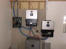
So..wait. One 30amp breaker feeding two 6000xps (see the wires combined in that j-box). Should have two 50amp breakers, each feeding a 6000xp.
Is the battery being charged when the grid breaker trips, may be in a charge cycle at the time the heater kicks on (no inverting, just passthrough). Remember this is either a charger or inverter but not both at the same time. This would explain why its functions fine when inverting battery.
Is the battery being charged when the grid breaker trips, may be in a charge cycle at the time the heater kicks on (no inverting, just passthrough). Remember this is either a charger or inverter but not both at the same time. This would explain why its functions fine when inverting battery.
What?? Do you only mean for its use of the AC (grid) input? I could see that, but not for the device as a whole, because any solar inverter-charger needs to do simultaneous inverting and charging for its PV input. Just trying to clarify for others that stumble on the thread one day.Remember this is either a charger or inverter but not both at the same time.
Thanks everyone for responding. I have the Victron II 3000 in my RV with load share so when I planed for the house I assumed it would also load share if needed so only ran a 30 amp 240 volt circuit to charge batteries??? And be there in case it needed help with a load. After receiving the 6000xp it said it needed a 50 amp grid circuit for pass through. So I figured design the house so that you will never load more then 50 amp or 12k. I did accomplish this the house runs below 2k 80% of the time and only when I need hot water will the 8k be drawn. Every time this happens the inverters are reading 60-65% usage and splits the load evenly with all 4 legs around 2.2k or so. Now if the the grid circuit is on it will draw as normal for maybe 1min and then switch to grid and pulls 100% of the load from grid. The inverters will shut down fans stop and an eps overload code W28 shows up. And of course the grid breaker will trip after about 1-2min. I guess my thought was if I needed a 50 amp grid circuit why would I need the 2 6000xps? And my brain can not get around why it will switch to grid with a 60% load?
No the grid is not charging it works flawlessly by charging batteries when it hits the setting of 20% soc. The 6000xps will only switch to grid power to feed loads when the 8k water heater turns on.So..wait. One 30amp breaker feeding two 6000xps (see the wires combined in that j-box). Should have two 50amp breakers, each feeding a 6000xp.
Is the battery being charged when the grid breaker trips, may be in a charge cycle at the time the heater kicks on (no inverting, just passthrough). Remember this is either a charger or inverter but not both at the same time. This would explain why its functions fine when inverting battery.
My intent was to only use the grid as a charger never thought it would try to use the grid to power loads? I have been very cautious never to exceed the 12k power available.What?? Do you only mean for its use of the AC (grid) input? I could see that, but not for the device as a whole, because any solar inverter-charger needs to do simultaneous inverting and charging for its PV input. Just trying to clarify for others that stumble on the thread one day.
timselectric
If I can do it, you can do it.
- Joined
- Feb 5, 2022
- Messages
- 20,087
Is it possible that the battery is disconnecting and causing the inverter to switch to grid?
Or if you are using closed loop communication, the BMS could be making it switch to grid.
You may need to get a second battery.
Or if you are using closed loop communication, the BMS could be making it switch to grid.
You may need to get a second battery.
I will look at the manual and try to figure out what you are saying. Funny thing about the generator I did put the 30 amp 240 volt circuit to the Gen input and set the max wattage for charging to 3k and it works like the grid power perfect. But once I turn on the hot water it reacts the same as grid now the inverters will pass the 8k load to the generator and I thought it was limited to 30amp 240 volt. And of course the same thing happens and breaker will trip on grid panel.I've read this a couple times and I think I might have an idea.
The input for the gid on the 6000xp is a 50amp circuit, which will pull up to 9000W at 240VAC at 37.5 amps according to the specs. But, you're feeding the grid circuit with an undersized 30amp breaker, which when you put an 8000W load on the inverter, which tries to pull that through the grid trips the breaker and potentially causes a fault.
To make matters worse, each inverter can take up to 37.5 amps, which is way more than your 30amp circuit can provide that you have split between your two inverters.
I think you probably need to disable any load from AC, and make sure the load is strictly from the batteries, which means they will always be discharging and charging.
See the top of page 22 in the manual, you basically need to eliminate the time in which the inverter would pass through from gid to load since your grid input is smaller than your load output.
I think you might also need to switch your inverter to working mode "AC Charge" see page 22/44 of the manual.
You could also possibly use the generator input, which would only activate when the batteries reach a certain SOC to charge up the battery. The difference with the generator input is that it doesn't function as an AC passthrough, and could only be triggered to on, when it's time to charge the batteries when configured correctly.
I guess that would be something to look at. But remember no grid circuit turned on and everything works as designed. The question I am trying to figure out is why it wants to use the grid circuit at 60% of load? No grid input and works perfect. Turn grid circuit on stops converting and goes to pass through?Is it possible that the battery is disconnecting and causing the inverter to switch to grid?
You may need to get a second battery.
timselectric
If I can do it, you can do it.
- Joined
- Feb 5, 2022
- Messages
- 20,087
It's a parameter that is being met, and causing the switch somewhere/somehow.I guess that would be something to look at. But remember no grid circuit turned on and everything works as designed. The question I am trying to figure out is why it wants to use the grid circuit at 60% of load? No grid input and works perfect. Turn grid circuit on stops converting and goes to pass through?
If the BMS commands a switch to grid, it switches to grid.
But if the grid isn't available, it can't so it doesn't.
I do believe that the problem is not enough battery.
Just wondering, would you think the system would shut down when I turn of the grid circuit if this was the case? This only happens if grid circuit is on?Is it possible that the battery is disconnecting and causing the inverter to switch to grid?
Or if you are using closed loop communication, the BMS could be making it switch to grid.
You may need to get a second battery.
I have the 280amp EG4 battery. Maybe I should just hook up a standard water heater?It's a parameter that is being met, and causing the switch somewhere/somehow.
If the BMS commands a switch to grid, it switches to grid.
But if the grid isn't available, it can't so it doesn't.
I do believe that the problem is not enough battery.
timselectric
If I can do it, you can do it.
- Joined
- Feb 5, 2022
- Messages
- 20,087
NoJust wondering, would you think the system would shut down when I turn of the grid circuit if this was the case? This only happens if grid circuit is on?
Because you aren't reaching the shutdown parameter.
timselectric
If I can do it, you can do it.
- Joined
- Feb 5, 2022
- Messages
- 20,087
That's fine for one 6kxp, but you have two.have the 280amp EG4 battery.
timselectric
If I can do it, you can do it.
- Joined
- Feb 5, 2022
- Messages
- 20,087
I would remove closed loop communication. And see if the issue goes away.
This will tell you if the BMS is commanding the switch.
This will tell you if the BMS is commanding the switch.
So maybe I can not get enoughI guess that would be something to look at. But remember no grid circuit turned on and everything works as designed. The question I am trying to figure out is why it wants to use the grid circuit at 60% of load? No grid input and works perfect. Turn grid circuit on stops converting and goes to pass through?
so maybe not enough current for an 8k quick hit. Like an AC load would do?I have the 280amp EG4 battery. Maybe I should just hook up a standard water heater?
I will try that after church and see what happens.I would remove closed loop communication. And see if the issue goes away.
This will tell you if the BMS is commanding the switch.
It’s starting to make since about battery. Do you think the w028 EPS overload fault is from the battery not inverter?I will try that after church and see what happens.
timselectric
If I can do it, you can do it.
- Joined
- Feb 5, 2022
- Messages
- 20,087
ProbablyIt’s starting to make since about battery. Do you think the w028 EPS overload fault is from the battery not inverter?
ScrotpusGobbleBottom
Corn Pop was a bad dude.
It feeds the loads with grid EVERY time its charging from gridNo the grid is not charging it works flawlessly by charging batteries when it hits the setting of 20% soc. The 6000xps will only switch to grid power to feed loads when the 8k water heater turns on.
@Madcodger The OP only has grid, no PV. Yes for AC Grid charging. The 6000xp and other off grid inverters can only invert or charge, not both at the same time. You can’t invert when AC grid charging. Need a hybrid for that capability.What?? Do you only mean for its use of the AC (grid) input? I could see that, but not for the device as a whole, because any solar inverter-charger needs to do simultaneous inverting and charging for its PV input. Just trying to clarify for others that stumble on the thread one day.
Last edited:
ksmithaz1
Solar / EV Junkie
These weird little edge cases are why I use an external transfer switch. The minute you go past a single inverter core design, the magic built-in switching gets complex. I would say though that a demand water heater is sub-optimal for solar.
Similar threads
- Replies
- 18
- Views
- 397
- Replies
- 2
- Views
- 170