diy solar

diy solar

Emporia Vue monitor in the EU - blue is not neutral. Now I know 🤦

Luk88

Solar Enthusiast
Joined
Apr 5, 2024
Messages
319
Location
Poland
So what happens if you give an Emporia Vue to someone who has been doing EU 3 phase electric for all his life, read the manual and still bloody connected blue to neutral through force of habit? (blue is phase 3 and white is neutral)

Now we know!

Of course it got connected right after 48A main breakers so it blew up. Literally.
Compress_20240623_023656_6478.jpg
Compress_20240623_023656_6779.jpg
The PCB was washed already. It was completely black from soot.

I've already ordered another one and redid the wiring in shame...

Amazingly it seems the only element visibly destroyed is the MOV. And the power plug the leads of which evaporated and covered the board. The little transformer does not appear shorted.

So tomorrow I'll try powering it up after some cleanup, on the bench of course, with a power limited(light bulb & variac) isolated circuit. Who knows maybe it works? Or perhaps only the AC side got destroyed? I'd love to get it working this weekend. Even despite the huge mess I had to to cause to put in all the sensors in my EU electric box.
 
So what happens if you give an Emporia Vue to someone who has been doing EU 3 phase electric for all his life, read the manual and still bloody connected blue to neutral through force of habit? (blue is phase 3 and white is neutral)

Now we know!

Of course it got connected right after 48A main breakers so it blew up. Literally.
View attachment 223964
View attachment 223963
The PCB was washed already. It was completely black from soot.

I've already ordered another one and redid the wiring in shame...

Amazingly it seems the only element visibly destroyed is the MOV. And the power plug the leads of which evaporated and covered the board. The little transformer does not appear shorted.

So tomorrow I'll try powering it up after some cleanup, on the bench of course, with a power limited(light bulb & variac) isolated circuit. Who knows maybe it works? Or perhaps only the AC side got destroyed? I'd love to get it working this weekend. Even despite the huge mess I had to to cause to put in all the sensors in my EU electric box.
Ouch..
 
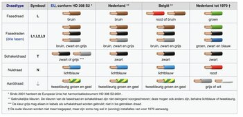
Correct in the eu =

There are 4 colors of wires used in electricity.
Blue = Neutral wire
Brown = Live wire
Black = Switch wire
Yellow/green = Earth wire

Vs usa .

Black, Red and Blue are used for hot wires and White is used as the neutral wire in a 120/208 V circuit. Brown, Orange and Yellow are used as hot wires and gray is used as the neutral wire in a 277/480 V. For grounding, regardless of the voltage, Green (or a bare wire) is used.

A systeem card in the eu.
If people looking for the information.
 

Attachments

  • Kleurcodes-installatiedraad-Ingenium-1024x497.jpg
    Kleurcodes-installatiedraad-Ingenium-1024x497.jpg
    90 KB · Views: 9
Anyway, the psu chip is blown on the board. Hooking up 5V to the rest of the circuit makes it start, register with "the cloud" but CTs don't work :-( it shows zero current.

I have the schematics so I checked all required voltages are present powering the adc, the CTs at. Still no dice. It is silly there is absolutely no way to troubleshoot with the emporia cloud app. I don't even know if it is supposed to show data live...

Amazingly it shows the voltage of 120V 🤦 no difference if I hook up other voltage to the sense lines. I would say the AD chip is broken, but again... No indication of errors and lights are happily blinking every second as if it's sending data. Is it getting any from the ADC? No idea.

Edit: I'm not seeing any activity on i2c between the main chip and the adc with an oscilloscope... Is this an indication the adc it's dead? Should the WiFi diode blink every second? If it can't talk to the adc should it not display ANY error in the "cloud"? Oh, so many questions and so little time. I'll solder in an i2c header and have a go with a logic analyser. If it takes over 1h it goes into the junk bin. I'm getting a new one (for $50) on Tuesday.
 
Last edited:
I guess I may as well update this thread with some additional info.

But first an important question for anyone that uses emporia Vue gen 2 in Europe? Is it really OK to connect voltage measurements to all 3 phases? It says 240V on voltage spec, but interphase voltage is more like 430V. I'd rather not blow up the next one that comes. So if anyone has an answer that would be great.

Anyone repairing an Emporia Vue gen 2 will find this github repo with schematics extremely useful https://github.com/emporia-vue-local/emporia-vue2-reversing/tree/master/kicad then to find out how comms with the ADC (, really another mcu) works this repo is invaluable (if one reads c code) https://github.com/emporia-vue-local/esphome/blob/dev/esphome/components/emporia_vue/emporia_vue.h

And pictures on this site: https://flaviutamas.com/2021/reversing-emporia-vue-2

The fact it is documented so well is the reason why I bought it. I'm not planning to use "their cloud" beyond initial testing.

So coming back to my repair. I hooked up a logic analyser to the i2c bus between the main chip (esp32) and the ADC mcu and indeed I can see the current readings change when I put more power through a light bulb with a variac. But"the cloud" shows zero, why? I think it is because there is no voltage reading so it disregard any other input.

With custom fiware it should be fixable, but at this stage it is more effort than it's worth so it goes into the "fix later" box.

I'm powering it through the programming header so it's not getting any AC on its voltage measurement input (I tried giving it few volts of AC 50hz from a signal generator with no difference). So either the voltage measuring input is fried or I'm missing something.
 

diy solar

diy solar
Back
Top