Are these all 12V DC or do you need an inverter to run any of them?
The core question is what voltage range can they handle and how do you stay in that range.
Also, regarding these cells vs LFPs, you really need a balancer for protection for non LFP. I mean, you want it for all chemistries. But, you have to have something to prevent runaway. The basic problem with cells in series is if one cell is failing or not charging enough, without a BMS, the charger does not know. The effect is it tries to overcharge the other cells. This can destroy the good cells, at a minimum. But, there is fire risk with the non-LFPs.
Until you commit to a chemistry and how many in series, you can't really pick a BMS. But, you do want to factor that in, and understand it is more critical with non-LFP chemistries.
But, going back to your loads, you typically start there and work backwards, as they define your minimum requirements, especially if using existing equipment. And voltage range is one of the parameters of your loads.
You then have to ask how you'll get to that voltage range. I really want to look into options for converting. I know you can do 24 to 12v easy. But, we see all the time products that have interesting battery configurations then convert to meet w/e requirements they have. But, no one I've seen has broken down how they are doing it. What chips or circuits are on their boards? What options are available for integrating such a circuit?
What I'd like to do is get a variable one, where I can dial the conversion up or down, and just use that for testing.
Your easiest route for now, though, is to test 3S. If it works for your loads, and you can live with the limited capacity range, then get a 3S BMS for protection, balance them and use the 3 cells that match the most, particularly on internal resistance. Keep the 4th as a spare or use it to power LEDs or USBs. I noticed a lot of the "DIY" power packs they are selling online just take 1S of 18650s of the 3.6V nominal, usually 4-8 in parallel. But, your cells look like they equal a good quantity of 18650s by the weight you listed of 0.72kg. You could hook up one of their circuit boards and charge via USB. The USB boards are yet another example of a voltage regulator built onto the circuit boards to provide stable boosted power.
One plus to the limited capacity range is more cycle life. So, you aren't really losing in the long run. It's more about how much you need in a 24 hour period and how long you can weather cloudy days, and that takes you back to your load requirements, and ability to recharge on a sunny day (PV capacity and charge rate).
I just weighed 10 18650s at 0.5 kg (in 5 plastic cases cuz don't really want to take them out lol) But that puts one of your cells near 15 of these. That extra cell would make a killer USB power bank.
") View attachment 2613
View attachment 2613
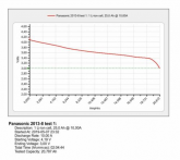
I'm guessing your cells are near 30aH. That's about 110WH per cell, or 330WH for a 3S. Your capacity will be less based on the bottom end of the voltage your load can operate at, and where that falls on the DoD chart you posted. So, if you can achieve 80% capacity, that's 264WH.