diy solar

diy solar

Need critique on my battery backup system

BatteryNut

New Member
Joined
Aug 13, 2021
Messages
20
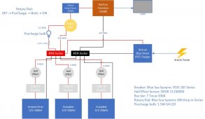
I'm looking to start a proper battery backup system instead of my current string of batteries tied to an inverter.
Currently, the planned loads are:
1) Sump pump, 280W running
2) Deep freezer, 60W running
3) IT Stack, 40W running (constant)
4) Wine fridge, 1.5W idle, 200W running

I have sourced all parts except the precharge bulb and the 4/0 wire.

If you have the time, please look over my design and the part selections and share your thoughts.

Your inputs are appreciated.

(jpg attached in case the pdf doesn't work for you. It works for me on my pc but not on my ipad)
 

Attachments

  • BatterySystem.pdf
    76.3 KB · Views: 19
  • BatterySystem.jpg
    BatterySystem.jpg
    64.6 KB · Views: 22
Last edited:
My VIctron 500 amp shunt is on the negative. For your system, I would place this between the negative bus bar and inverter.

Not sure of the purpose of the light except always on.

I have no idea what kind of batteries those are, like lithium or FLA,, ETC. A lot of batteries are not deigned to be on a float charge forever and then used during an odd power outage. That could cause them to die early.

I don’t like breakers on batteries, unless they have a high AIC rating. I prefer ANL fuses except for lithium which would be class T.

For reference, my 12 volt system running a microwave draws 1800 watts from the inverter, but with DC to AC conversation loss pulls closer to 2100 Watts from the batteries. My Victron Shunt shows the batteries pulling 155 amps.

I like the 4/0 wire.
 
The precharge light is there as an indicator of the charge status of the inverter's DC link capacitors. Capacitors behave as short circuits when fully discharged and gradually approach open circuit as they're energized. I placed the bulb there so when the rotary switch is on precharge, a lit bulb indicates capacitor charging and an unlit bulb indicates fully charged status.

The batteries are all LiFePo4 with dedicated BMS built in. They all have a nominal continuous max discharge rating of 100A, which is why I thought the 100A breakers would suffice.

I'll take your advice on the placement of the shunt.
 
You have 3x 4 awg cables from battery to bus bar, but 0000 from the in bus bar to inverter. That's not the same amount of copper on each side of the bus bar. I'd probably make a change there.

The breaker/fuse thing has to do with short circuit current. In the case of failure you might need a fuse that can stop over 10,000 amps. Way past the battery's rated current (it would obviously damage the battery) but lithium can put out a lot of current into a dead short. Without knowing the specifics of the BMS, I would doubt the internal BMS is rated built to stop a massive short. Most just use a MOSFET and it isn't going to stop thousands of amps.

There are 100 amp fuses rated to 20,000 amps (AIC or amp interrupt capacity)
 
You have 3x 4 awg cables from battery to bus bar, but 0000 from the in bus bar to inverter. That's not the same amount of copper on each side of the bus bar.
Is this really an issue? I plan to use class T fuses in addition to the 100A breakers, which will now only serve as manual disconnects.
 
Is this really an issue? I plan to use class T fuses in addition to the 100A breakers, which will now only serve as manual disconnects.

Class T fuses should give you plenty of interrupt current.

For the wire gauge it's only an issue if you are moving enough current. If you're not going to max out the batteries, it would be fine.
 
Is this really an issue? I plan to use class T fuses in addition to the 100A breakers, which will now only serve as manual disconnects.
Based off ampacity, 4 AWG wire by this chart is not rated to 100 amps. I'd recommend 2 gauge to 1/0. The size I'd choose would be based off how long I want to spend at 100 amps. To me 1 AWG is best, but I have trouble finding that odd size at my local home dept.
1631218828050.png

You could get a 4 AWG wire rated for 100 amps, but the insulation rating would be higher than the 90 ° C listed on this chart. I like to keep insulation rating at 60° C for a couple reasons. I don't want it getting so hot it burns me. 75 ° C may burn you, but I'm sure 90 ° will. The 4 AWG wire is probably 105° C+ and could boil water. Another is the resistance of the wire goes up as it gets hotter, and getting a thicker wire gives me more leeway for that.
 
Back
Top