diy solar

diy solar

Building a DIY Lifepo4 charger

brandnewb

Going for serious. starting as newb
Joined
Oct 6, 2021
Messages
2,425
Location
-5m altitude from sea level
Would it be feasible/advisable to DIY a LifePO4 battery (pack) charger?

I am considering DIYing the following;

240V/50Hz(AC) power outlet -> 2 string cable -> Full Bridge Rectifier -> DC step down transformer (Transform DC Voltage to a voltage that matches with the battery pack down the line) -> charge battery pack with the power that is available from the power outlet.

If that is a good idea then can I do the same concept but then use a 3 phase source?

400V/50Hz(AC) power outlet -> 3 string cable -> Full Bridge Rectifier -> DC step down transformer (Transform DC Voltage to a voltage that matches with the battery pack down the line) -> charge battery pack with the power that is available from the power outlet.

Or would any of those ideas result in bad stuff?
 
No, honestly. Two salient characteristics (drawbacks) of AC and DC: AC you can't store, DC you can't transform.
So obviously you'd want to put the transformer before the rectifier bridge.
After which you'd have a vaguely unregulated pulsating current.
After which :·) you'd want to
a) smoothen the pulsating current down - at least a bit - and
b) regulate it to charge the battery properly.

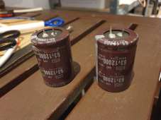
One way to do that (smoothen it) would be with capacitors.
One way to do the other (regulate it)... could be... if you manage to get the pulsating current smooth enough, feed it into an MPPT solar controller, which will take care of the proper charge - providing it's properly configured for your battery.

The main question - to start with - would be: what amperage would you want?
 
Would it be feasible/advisable to DIY a LifePO4 battery (pack) charger?

I am considering DIYing the following;

240V/50Hz(AC) power outlet -> 2 string cable -> Full Bridge Rectifier -> DC step down transformer (Transform DC Voltage to a voltage that matches with the battery pack down the line) -> charge battery pack with the power that is available from the power outlet.

If that is a good idea then can I do the same concept but then use a 3 phase source?

400V/50Hz(AC) power outlet -> 3 string cable -> Full Bridge Rectifier -> DC step down transformer (Transform DC Voltage to a voltage that matches with the battery pack down the line) -> charge battery pack with the power that is available from the power outlet.

Or would any of those ideas result in bad stuff?
I assume that by DC step down transformer you mean a DC-DC converter. Buck converter in this case.

This would be a non isolated power supply. You can do it but a failure in the converter will very likely result in massive damage to the battery and everything that's connected to it and a fire.

Also being non isolated means that there is no galvanic isolation, so all terminals in the battery, plus whatever is connected to it should be treated as live at mains voltage (Shock hazard), so it would require the entire system being inside an insulated enclosure.

Also your DC should not be grounded, because otherwise depending on how you connect this power supply AC side you will cause a short circuit as well.
 
Also your DC should not be grounded, because otherwise depending on how you connect this power supply AC side you will cause a short circuit as well.
ok, no grounding then. basically I am trying to create a crude Switching power Supply with massive force. Not at all fine tunable and the switching aspect will be changing the buck converter
 
Also being non isolated means that there is no galvanic isolation, so all terminals in the battery, plus whatever is connected to it should be treated as live at mains voltage (Shock hazard), so it would require the entire system being inside an insulated enclosure.
thank you for the heads up. well understood. I can make an enclosure
 
A DC-DC (step-down) converter - unless it just dissipates the excess voltage, which is as primitive as it gets - what it does is convert the DC into AC, "transform" that, and then re-rectify it. You can work out for yourself how intelligent and efficient that is, if you have AC to start with.

Now, 140A is big. More like huge. At... what (nominal) voltage? 24?
I wouldn't really try. You could aim for... 40-50 and still have to deal with some serious components, some heat dissipation, wire sizing, quite a few hurdles. What sort of battery are you planning to charge? From what source?

Man, I had a 50A charger some 15 years ago. It had wheels :·)

[EDIT] When I say "transform", they don't, really. Usually they use PWM (Pulse Width Modulation) which takes the AC square wave and makes the "periods" (squares) longer or shorter... look it up. Still, it's absurd to do that if you have AC to start with, and can just use a good transformer.

----------------------------------------------------------------------------------

The stove rig, it was very tinkerish, I agree. But effective. I had the pressure cooker. The valves were shot. I though, hey, why don't I put some tubes in there and run the hot water somewhere else. It took a bit of experimenting, made it work.
.
 
Last edited:
You can work out for yourself how intelligent and efficient that is, if you have AC to start with.
I am not known for intelligence ;( I'd assume that transforming AC to DC to AC is just a step too much with all the losses that go along with it.

Now, 140A is big. More like huge. At... what (nominal) voltage? 24?
Any. wether it is to charge a single LifePO4 cell at 3.2V or a pack 16S (48V) or what ever. I have asked on a different thread whether there is a use case for a 400V battery pack but the jury is still out.
The stove rig, it was very tinkerish, I agree. But effective.
Yes. Effective is what is the most important
 
Would it be feasible/advisable to DIY a LifePO4 battery (pack) charger?
When you consider that any charger is just a power supply with a Constant Current phase and a Constant Voltage phase then it is feasible. I do not know if it is practical especially if you wanted to be able to adjust the settings and add features found in many charge controllers or chargers already integrated in many inverters.
 
Well, say you aim for 40A. Still pretty big.
Say you use a double-coil toroidal transformer, that makes 70V AC on one coil and 15 on the other... forget it actually, to charge individual cells you'd have to make a separate one. Say you have a transformer that makes some 60V AC. Rectify it and smoothen it out. Plug that into a 50A MPPT and see how it deals with it. If it doesn't like it, smoothen out the pulsating current some more.

Or, just feed the pulsating current to the battery, at some 10V over nominal, through an ammeter, and watch it like a hawk. In that case, you could use a double-coil transformer - or two of them, one for 48V, one for 24.
If the MPPT works, it will deal with higher voltages, so you might get away with just one coil.

In any case, you would need to have fuses/circuit-brakers, properly sized wires, dissipate some heat, and have a decent basic knowledge of electricity.
 
if it is practical especially if you wanted to be able to adjust the settings and add features found in many charge controllers or chargers already integrated in many inverters.
I was looking for a 200V140A switching power supply and actually found one. But then realized that if I bought it I would end up in a huge fight with my wife. i.e. far too expensive ;(
 
Just as a note, I charge my batteries with the all-in-one inverter/charger. From a generator.
Not very often but last night I did, we haven't seen any sun for a while.
It does 20A (at 24V), and the fans are more on than off. Good thing it's outside :·)
.
 
But then realized that if I bought it I would end up in a huge fight with my wife. i.e. far too expensive ;(
There is a concept that says you can pay me now or you can pay more later. I don't know your skill set with regard to domestic relations or electronics but it's your choice. As others have said if you ruin your batteries you will have a bigger domestic relations problem. It is a risk management decision.
 
can you please rephrase? I am not sure I follow yet
You have admitted that you do not have the skill set. Therefore it is likely you will make mistakes that will cost you more to fix your mistakes than the original cost of the charger. Sweeping it under the carpet may solve your domestic relations problem but is not the optimal decision.
 
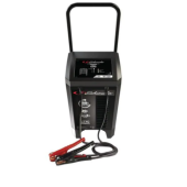
A typical automotive heavy-duty battery charger, like you find in car repair shops, usually looks something like this and costs some 300- 600 € depending on amps. Say 300 for 50A.
You might find a used one.
charger.png
 
Perhaps you could spend some time optimizing what you actually need.
I'll add some context. I should have lead with that I realize now.

I have recently gotten 16 3.2v 280A cells and I am planning to get a whole s$&tload more.

I think I need a battery bank that is quite potent as to make sure I do not get surprised again (like what we had just now with version 19 of our beloved virus friend) ever. And not be able to run my home and make sure my family does not notice anything is wrong in terms of comfort in our home.

Since I am a cheap ass and need to learn how to DIY I bought my very first 16 cells from our friends in the east. Shady at best so I need to quickly be able to test them.

Not only that, I plan to buy many more of cells. Maybe even enough to get to 400V (125S) if there is an actual use case for it.

What I think I need is a way to as quickly as possible test cells/packs of cells.

If I am not mistaken that means getting up to 3.6525v as fast as possible. And then running a load at 1C (280A)

THe source I have gotten the cells from is not known, only the go between (aliexpress). And many of us have learned the hard way that ali is not our friend when it comes to disputes. There is a narrow time margin between delivery and complaint hence my wish to go full force.
 
So you're planning to spend half of Liberia's GDP on cells and then save a hundred bucks on a charger? :rolleyes:
hahhaha I am not sure I can follow that yet ;( No I plan to make it feasible to go to insane(TM) levels step by step over time. IF I need to spend 8ke on a charger than 2 things will happen.
1) sleep in the garage because my wife has outcast me
2) I have learned nothing on how stuff actually works.

I am prepping for a storm that is even greater than V19
 
You guys input has set me on a different path. I will try and find a 0-400v variac and see if I can reason that.

Would that make for
variac -> fbr -> cell(s)?
 
Nailed the transformer part in the meantime.

According to an excerpt of a research paper I do not have to worry about the DC ripple after rectifying


Does anyone know research that shows the contrary?
 
Btw, when charging a single cell, or cells in parallel at 125 amps. The amps will go down to 0(.0001) amps once cell(s) are at the charge voltage yes?
 
Btw, when charging a single cell, or cells in parallel at 125 amps. The amps will go down to 0(.0001) amps once cell(s) are at the charge voltage yes?
Most battery chargers behave the same way. The charger tapers off the current in order to maintain the constant voltage. It doesn't matter if the cells are parallel or in series.
 
I will be using a DIY power transformer to charge the cell(s).

I am a little worried though that things go wrong because I missed something. So I am really hoping that the amps will reduce as the cell(s) reach their target voltage. Can anyone confirm?
 
Back
Top