I do not have a battery rack with buss bars in it so I can't use the short #4 cables that come with the batteries. I have two batteries and two inverters in split phase for now and the wiring needs to be about two to three ft long to the buss bars. Is #4 cable still ok with the added couple of feet in length and do the battery cables coming from the batteries Before the buss bars have to be equal in length as well as the cables coming from the buss bars to the inverters.


You are using an out of date browser. It may not display this or other websites correctly.
You should upgrade or use an alternative browser.
You should upgrade or use an alternative browser.
Wire sizing for eg4LL batteries to buss bars
- Thread starter bones1
- Start date
Ampster
Renewable Energy Hobbyist
I am not sure what you mean by buss bars equal in length? My negative cable from battery to inverter is a different length than positive cable. The negative cable also has a fuse, a shunt and a circuit breaker in the path. Only the cables that parallel batteries or cells need to be equal length.Before the buss bars have to be equal in length as well as the cables coming from the buss bars to the inverters.
Last edited:
John Frum
Tell me your problems
- Joined
- Nov 30, 2019
- Messages
- 15,230
#4 pure copper wire with 105C insulation is good for 150 fault amps.
150 fault amps *.8 fuse headroom = 120 service amps.
What is the continuous rating on your your inverters?
Lets say these are the popular 6500 watt 48 volts ones.
6500 ac watts / .85 conversion factor / 48 volts low cutoff = 159.31372549 service amps
159.31372549 service amps / .8 fuse headroom = 199.142156863 fault amps
199.142156863 fault amps * 2 all in ones = 398.284313725 fault amps
Your batteries, BMSs and wires are woefully underspec.
Ampster
Renewable Energy Hobbyist
That is correct for your assumption of a 6500vWattn Inverter being run at capacity. I did not see where the OP mentioned his inverter size so we don't know.Your batteries, BMSs and wires are woefully underspec
John Frum
Tell me your problems
- Joined
- Nov 30, 2019
- Messages
- 15,230
That is correct for your assumption of a 6500vWattn Inverter being run at capacity. I did not see where the OP mentioned his inverter size so we don't know.
It was just an example so that OP could do the math whatever inverter he has.
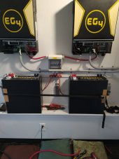
They are two 6500watt EG4 inverters in split phase. I have two 48-volt eg4 batteries to use. These batteries have/ come with foot long #4 cables for use in their battery rack, which I didn't purchase. The terminals on these batteries are very small, a 2 ought lug wont fit. They used #4 but I think that is too small to use without using their battery rack. I have 2ought running from the inverters, thru breakers, and to a bus bar with 3/8 studs. So from that buss bar to the two batteries which cables to use keeping in mind the tiny battery terminals.
Last edited:
I heard that the pos and neg cable from the buss bars to the inverter had to be the same length.I am not sure what you mean by buss bars equal in length? My negative cable from battery to inverter is a different length than positive cable. The negative cable also has a fuse, a shunt and a circuit breaker in the path. Only the cables that parallel batteries or cells need to be equal length.
Ampster
Renewable Energy Hobbyist
I have heard that also but there is no electrical reason why that would be necessary in a serial connection. It cannot be for wire resistance reasons because people put shunts, breakers, and fuses on just one leg without issue. Those things all add resistance.I heard that the pos and neg cable from the buss bars to the inverter had to be the same length.
Perhaps the context where we have heard it is when people do not distinguish between serial connections and parallel connections. It is very important in parallel connections that the resistance between parallel batteries or cells be very close.
cs1234
Solar Wizard
- Joined
- May 9, 2022
- Messages
- 2,790
I don't believe that to be the case. I think in some of @Will Prowse videos, he even mentions that they don't have to be and shows them being different lengths.I heard that the pos and neg cable from the buss bars to the inverter had to be the same length.
You only need to keep the lengths of cable the same in between batteries in parallel on a bus bar to keep them "equal" as far as which ones are hit the hardest when being used. If you are hooking the batteries up to a bus bar for parallel, you would want each battery to have the same length cables from the battery to the bus bar. The positive and negative cables could be different lengths, even for each battery, but each battery needs the same total length / type of cable to complete it's run from positive to negative as a circuit or one of the batteries will be preferred over the others.
This assumes of course that each battery is also at the same state of charge to begin with, otherwise one will be favored over the others at first regardless because it likely has a higher voltage. If the total cable circuit length is equal between each battery to the bus bar, they should level out as far as their charge goes over time and then be used equally.
TLDR.. keep the positive and negatives cables from each battery to the bus bar the same length. The positive and negative cables from the bus bar to the inverter can be different lengths, it does not matter.
Ampster
Renewable Energy Hobbyist
There was another thread asking the same question. I did not follow it so I can't offer any suggestions other than to try to find a narrower lug. It is the surface area of the lug that matters. Without seeing a picture and I had to find a solution I would trim a lug or make up a short bus bar that would fit on the battery and cover the entire contact area on the battery teminal. The other end of the very short bus bar would accommodate the larger lug of the wire size needed for your system. It is important to use a lug with the same hole size as the stud on the connection or you are losing valuable contact surface are which, as I mentioned is important to reduce resistance. i do not know that battery but some have two lugs and if that is the case you can use two pieces of smaller wire. Also the wire size to parallel bateries does not have to be the same size and the wire from the bus bar that parallels the batteries to the inverter. Just be sure and use the right size fuse to protect the wire based on the size of the wire.So from that buss bar to the two batteries which cables to use keeping in mind the tiny battery terminals.
Last edited:

Ampster
Renewable Energy Hobbyist
It depends on how much current you expect to draw from each battery. Is there over current protection in the battery? If not are you planning on putting a fuse on each battery?So Try to find a way to use 2 ought cable instead of #4 from these tiny battery terminals to the buss bars.
cs1234
Solar Wizard
- Joined
- May 9, 2022
- Messages
- 2,790
Aren't those batteries rated for 100amps usually? How high do they peak before they shut off? 2/0 sounds pretty large for a 100-150 amp load through to a bus bar. Not that there is anything wrong with using more copper than you have to other than cost and waste.It depends on how much current you expect to draw from each battery. Is there over current protection in the battery? If not are you planning on putting a fuse on each battery?

Ampster
Renewable Energy Hobbyist
Use the Ampacity tables to find the right size wire for 125 Amp breaker. You have some slack because the BMS will probably cut out first but you do not want to count on the BMS being OCP.. @John Frum did the calculation above for the battery wiring based on 100 Amps so whatever works for that 125 Amp breaker..Did you find bigger lugs that fit? As mentioned earlier more copper doesn't hurt.I have them connected with #4 going to the buss bars but it looks so small.
Use the Ampacity tables to find the right size wire for 125 Amp breaker. You have some slack because the BMS will probably cut out first but you do not want to count on the BMS being OCP.. @John Frum did the calculation above for the battery wiring based on 100 Amps so whatever works for that 125 Amp breaker..Did you find bigger lugs that fit? As mentioned earlier more copper doesn't hurt.
Similar threads
- Replies
- 6
- Views
- 388
- Replies
- 0
- Views
- 171
- Replies
- 28
- Views
- 2K