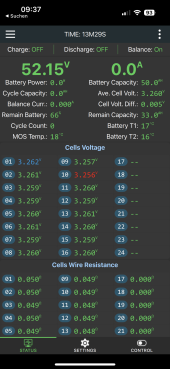
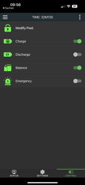
Hi! Is there some way to reliably and automatically start a JK-B2A24S15P? When the external inverter-charger itself requires battery power before it will start up?
Working on the setup, I had initially assumed it is enough to have the thin lead "B+ BMS Power" (and 16S lead) hooked to the +48V terminal of the LFP. Alas, the entire setup stayed dead. After triple-checking the manuals, JK mentions "The protection board does not have a power-on control switch, and it is designed as a charging activation mode, that is, after the battery is assembled, a charger needs to be connected to make the protection board work."
Alas number 2, to my surprise, my hybrid inverter (Steca Solarix PLI 5000-48) appears to be designed to start up *only* from battery, regardless of PV and/or grid input presence. Once the Solarix inverter actually runs, it is able to charge from PV and/or grid, and can thereby "sustain" itself.
Ergo: the hybrid inverter and BMS are both designed to wait for the other to start first :-( I messed up device selection...
One test I did was to bypass the JK-BMS protection board by tying its B- and P- leads together. The hybrid inverter started fine. The BMS remained off, of course.
The Solarix draws about 20W from battery in quiescent mode. This is quit a lot. Another test to start the JK-BMS, still todo, is to get a high-wattage 50 Ohm(?) resistor and permanently wire it across the B- and P- leads.
That *might* pass the ~20W needed by the inverter to power up and operate, and then in presence of PV input, the inverter should begin "charging", thus raising the voltage by >2V higher than the LFP voltage as required for the JK-BMS to start. After that there *should* be proper LFP via the then operational BMS protection board.
Otoh this potential 50 Ohm high-wattage resistor setup seems a bit stupid -- semi-bypassing the battery protection...
Is there some other, more elegant way to get this mess working?
Somehow use the PV input (~82V OC) to bootstrap the JK-BMS? Maybe 10k resistors to the JK-BMS B- and P-, and some protective 68V Zener diode or such acorss?
Or some other...?
Has anyone run into this same issue?


