I'm going to start this with a basic diagram of the electrical system I'm working with. The vehicle I'm working with is a CUCV M1010 which was a military field ambulance. It came with two alternators to begin with but the originals were both 24v and used a terrible system to try to regulate 12v, it always failed. It is currently outfitted with 12v 160a alternators which has proven to be a extremely reliable solution.
I am utilizing the wiring a power distribution panel which was rated at 200a in the back of the truck. All of the fuse numbers are what the circuit is rated at, not the actual draw. The Anderson plug was a separate circuit as well that was rated at 60 amps which I am using to essentially to feed the panel for solar. Yes AC is listed, it currently uses an engine driven compressor so only utilized when the engine is running in current set up. Would I like to change that, possibly but that's down the road, and a long discussion. The air compressor is a similar thing, mainly utilized with the engine running but a just in case on battery, 24v for less load.
Things I currently have:
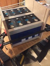
280Ah cells from Xuba- ordered
Blue Sea ACR 7623
200a circuit breaker
Needed:
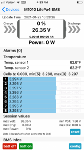
BMS
Solar Panels- been looking at 110 and 170 Sunpower panels for weight and clearance on the roof but I know the thoughts on flexible panels- up for consideration
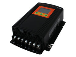
Charge Controller- plan was 4 panels, 2 in series for voltage then parallel into the controller
Inverter- I am trying to do as little with one as possible so I don't plan on a large one. Not on the diagram...
24v to 12v buck converter- probably for stereo, not sure what else
Things needing power: Fridge, Roof Fan, Stereo, Laptop, Phone charger, Heater, TV, all LED lights
Looking for simple reliability. Open to discussions...
John
") . So if the battery was run way down charging from both could be beneficial. This is where the ACR would falter as it can't regulate amps like a DC-DC can.
. So if the battery was run way down charging from both could be beneficial. This is where the ACR would falter as it can't regulate amps like a DC-DC can.