diy solar

diy solar

9.8kW DIY Grid-tie - Question about Metal Clad cable in attic and general feedback on my design?

As for ampacity of the #10 - If this table is right I think I should be OK?
View attachment 162912
30*.8= 24 and my short circuit current is 11.54a. Run in series, each string with 11 panels, it should be open circuit voltage 538v, 11.54a. I suppose I could even drop to 12awg? I don't have the specs of this particular MC, but looks like solid copper if that makes a difference.
So don't shoot the messenger, but ...

You need wire of basic ampacity of 11.54*1.25*1.25 = 18A. That is then derated for the fill (factor of 0.8), or 18/0.8 = 22.5 A. Then, the temperature derate. I don't know what type of wire is in the MC or your attic temperature, but assuming 75C wire and an attic temp of 130F, the temp derate is 0.67. So now you need 22.5/.67 = 33.6A, just over the 30A given in the amapcity table. Even with 90C wire, you're still over what #10 allows, but still just slightly.

BTW, the extra 1.25 comes in because of cloud edge effects.

I think MC is usually 90C but that should be confirmed.

Is it required to use attic temp of 130F? Can ASHRAE 99% ambient outdoor temp be used for attic, or is that nonsense since it is cooking from the roof and not ventilated like the outdoors are?

I know the rooftop derating is more specific and prescriptive.
 
FWIW, I kind of feel a minor attic ambient fudge is OK… other stuff like mechanically protecting the high voltage circuit and sorting out the busbar feels more important.
 
So don't shoot the messenger, but ...

You need wire of basic ampacity of 11.54*1.25*1.25 = 18A. That is then derated for the fill (factor of 0.8), or 18/0.8 = 22.5 A. Then, the temperature derate. I don't know what type of wire is in the MC or your attic temperature, but assuming 75C wire and an attic temp of 130F, the temp derate is 0.67. So now you need 22.5/.67 = 33.6A, just over the 30A given in the amapcity table. Even with 90C wire, you're still over what #10 allows, but still just slightly.

BTW, the extra 1.25 comes in because of cloud edge effects.

It is the final ampacity after 1.56 that absolutely has to be below 30A (small conductor ampacity limit for #10 copper)

You can go up to 40A with 90C wire IIRC after the CCC and ambient derating
 
I don't think the maximum ambient air temp will cut it. I agree that the attic temp derate issue is kinda minor, but somewhere in the thread is something about meeting with the AHJ and maybe doing a preliminary review. I just don't want him blindsided by it.
 
I wonder if taking the midpoint between ambient and the temp you’re supposed to use for above roof is a reasonable guess.

My calculations:
11.54*1.56=18A (fine for independent unbundled #12 BTW)

90C copper #10 max ampacity = 40A

40*.76*.8=24.3A

#12
30*.76*.8=18.24A which is also OK.

Note. If you switch to say those newer lower voltage/higher current 56cell panels then 12/4 MC will not work. Personally I would stick to #10 for the extra safety margin in many dimensions. Probably won’t see an efficiency improvement, and #12 isn’t really meaningfully simpler to deal with.
 
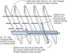
Running board

1692142528631.jpeg


Post 5 here has some good pictures showing running boards and guard strips
 
You need to multiply ISC by 1.56

1.25 for continuous and 1.25 for meteorological conditions boosting output above STC.

Solid vs stranded makes no difference.

Do not consider aluminum for this application.
Thank you for fixing my calcs! Either way I’m under 20a, but I figure 10awg may be slightly better for line losses so I’ll stick to my original plan.
 
OK I looked at your split bus a bit more

I would use the sum rule for the top half of your panel and 120% on the bottom half of your panel. I think the panel bus rating is 200A for the top section and 100A for the bottom section. POCO likely does not care if you put the new backfeed breaker on the top section, however this could be a situation where AHJ or POCO could complain b/c of how it interacts with split bus being grandfathered in.


You have the option of feeding the solar into either the top part or the bottom part. Looks like you want to do the bottom section

Bottom section: 70 + 40 < 100 * 1.2 (as you have in first post)
Currently you have 25+30+60+70+40 = 225A in the top section. This exceeds the 200A rating on the label.

You would need to move some of the loads off the top part into either the bottom section or a new subpanel hanging off the top section. It is probably cleaner to do it in the top section. You would have to do a load calculation to figure out which of the top panel loads can be combined into a subpanel with a smaller breaker than the sum of the loads (since you need to remove 25A of breakers from the top).

There is a section in the sticker that says TQAL-AB - max 110A. It also says 100A for the max breaker for bottom section. Somewhere between 100A-125A is the max breaker you can put on the top for another subpanel.
 
Back
Top