pellicle
retired ex-professional dingbat
Hi
I've played a little with some systems for camping (powering a 12V fridge) and have a reasonable understanding of the basics, however my problem is perhaps a little complex so I'll try to explain it as best I can.
I want to charge a battery (a collection of cells of course) and use that energy for a 240V inverter in my shed. I've done some analysis of my needs (with a power meter when using the tools in question) and my biggest single draw is the 1200W vac (although the drop saw is pretty high in transient too) most other stuff is low power. I did a "typical" days work through a power point monitor and worked out that in a heavier day I end up using 200Wh, which is of course reasonably modest when spread out. I don't work every day like that and mostly its a (electronics) soldering iron, charging some Lithium battery packs now and then and that's about it.
My question however relates to the use of the controller, the battery, the load and charging.
So, some more details. I decided to run 24V (so two batteries linked in series to make one battery) as what I feel is a sufficient step up in volts to halve the amps sucked by the inverter. I estimated that my vac would draw about 50Amps from a 24V system and after assembling it and running some tests and found that it was ball park that (some inevitable inefficiencies notwithstanding). I'm pretty comfortable that the system can tolerate that for the 5 or 10 min that I usually run the vac. I'm of course using heavy gauge wire (AWG 3) on a very short run to the inverter. There is no sign of heating under load (thermal camera).
I don't believe that I can run that from any controller that I can think of (open to input here) so instead I have the inverter wired to the battery and the solar controller output wired to the battery in parallel. I have seen this sort of arrangement used by others. My system is:
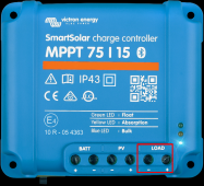
I have in the past tested this controller with running a 12V Engel fridge from the controller "load" using 2 100W 22Voc panels in series and it worked like a bought one, gracefully handling the increased voltage and properly refactoring the power to give a good charging power to my (single) 12V 100Amp battery while not changing charging as the fridge cycled in and out of load. The amps measured on the panel side scaled as one would expect under the load.
This was what I call 'perfect' as it allowed my battery to be fully topped up (on a sunny day) to cope with the evening discharge only (via the "load"). However when I experimented with running the Engel of the battery directly the system was always lagging behind topping off the battery during the day (not unexpected).
I wondered how this would work when I went on to my next phase (power to my shed). Because while a 250W panel (delivering perhaps a real 200W when all factors are weighed in) should be able to fully power a 110W draw I had my strong suspicion that it would not because of the above discrepancy between using the "load" output VS only the charging.
The above behaviour showed itself in an experiment over the weekend when we had a scheduled power outage here. I decided to use the system to power my household fridge which draws about 110W when its running and over a 24H period sucks about 2kWh (not unexpected). So I dragged the batteries and inverter and a panel (as above) out of the shed and sat it at the best location in the yard (*full sunlight, sunny day) to run the fridge through a standard 10 meter extension cable from the inverter.
I started with the system nicely charged. At peak load times the fridge (meaning the inverter) was pulling 4Amps out of the battery but the measurement of Amps (clamp meter) showed that only 2A was going from the controller to the battery (probably because its algo was saying at that V apply this charge pressure. Now while the load from the fridge (lets call that 4A) was well within the 20A that the controller can provide it would pop its little fuse if that was not controlled as to what could draw.
Naturally the battery fell down to 24.5V at end of the experiment (which ran from 8am to 3pm).
So how can I avoid this issue without (say) using 2 inverters, one off the load for lighter drains and one off the battery for heavier draws?
Is there a better practice for this?
Thanks in advance
I've played a little with some systems for camping (powering a 12V fridge) and have a reasonable understanding of the basics, however my problem is perhaps a little complex so I'll try to explain it as best I can.
I want to charge a battery (a collection of cells of course) and use that energy for a 240V inverter in my shed. I've done some analysis of my needs (with a power meter when using the tools in question) and my biggest single draw is the 1200W vac (although the drop saw is pretty high in transient too) most other stuff is low power. I did a "typical" days work through a power point monitor and worked out that in a heavier day I end up using 200Wh, which is of course reasonably modest when spread out. I don't work every day like that and mostly its a (electronics) soldering iron, charging some Lithium battery packs now and then and that's about it.
My question however relates to the use of the controller, the battery, the load and charging.
So, some more details. I decided to run 24V (so two batteries linked in series to make one battery) as what I feel is a sufficient step up in volts to halve the amps sucked by the inverter. I estimated that my vac would draw about 50Amps from a 24V system and after assembling it and running some tests and found that it was ball park that (some inevitable inefficiencies notwithstanding). I'm pretty comfortable that the system can tolerate that for the 5 or 10 min that I usually run the vac. I'm of course using heavy gauge wire (AWG 3) on a very short run to the inverter. There is no sign of heating under load (thermal camera).
I don't believe that I can run that from any controller that I can think of (open to input here) so instead I have the inverter wired to the battery and the solar controller output wired to the battery in parallel. I have seen this sort of arrangement used by others. My system is:
- 2 x 12V automotive batteries RC = 90
- 60cell 250W panel (claimed, measures close enough)
- Voc = 37.51V
- Vmpp = 30.4V
- Impp = 8.22A
- Isc = 8.88A
- eBay MPPT 12/24V 20Amp controller (seems to behave well)
- eBay AU$210 2000W (4000W peak) inverter (AU$ because I'm in Australia)
I have in the past tested this controller with running a 12V Engel fridge from the controller "load" using 2 100W 22Voc panels in series and it worked like a bought one, gracefully handling the increased voltage and properly refactoring the power to give a good charging power to my (single) 12V 100Amp battery while not changing charging as the fridge cycled in and out of load. The amps measured on the panel side scaled as one would expect under the load.
This was what I call 'perfect' as it allowed my battery to be fully topped up (on a sunny day) to cope with the evening discharge only (via the "load"). However when I experimented with running the Engel of the battery directly the system was always lagging behind topping off the battery during the day (not unexpected).
I wondered how this would work when I went on to my next phase (power to my shed). Because while a 250W panel (delivering perhaps a real 200W when all factors are weighed in) should be able to fully power a 110W draw I had my strong suspicion that it would not because of the above discrepancy between using the "load" output VS only the charging.
The above behaviour showed itself in an experiment over the weekend when we had a scheduled power outage here. I decided to use the system to power my household fridge which draws about 110W when its running and over a 24H period sucks about 2kWh (not unexpected). So I dragged the batteries and inverter and a panel (as above) out of the shed and sat it at the best location in the yard (*full sunlight, sunny day) to run the fridge through a standard 10 meter extension cable from the inverter.
I started with the system nicely charged. At peak load times the fridge (meaning the inverter) was pulling 4Amps out of the battery but the measurement of Amps (clamp meter) showed that only 2A was going from the controller to the battery (probably because its algo was saying at that V apply this charge pressure. Now while the load from the fridge (lets call that 4A) was well within the 20A that the controller can provide it would pop its little fuse if that was not controlled as to what could draw.
Naturally the battery fell down to 24.5V at end of the experiment (which ran from 8am to 3pm).
So how can I avoid this issue without (say) using 2 inverters, one off the load for lighter drains and one off the battery for heavier draws?
Is there a better practice for this?
Thanks in advance


