diy solar

diy solar

Automatic Transfer Switch in system

RoadTurtle

Solar Enthusiast
Joined
Mar 30, 2022
Messages
368
5th wheel came prewired with ATS. I had an EMS installed which sits between rear power inlet and ATS.

To make my life easier and for a couple other reasons, I wired a front power inlet to the MP, and it's output is wired into the ATS from the preinstalled generator wiring.

Rear inlet -> EMS --> ATS \
..........................................................Panel
Front Inlet --> MP --> ATS /

Will I pass or fail the smoke test if I leave the MP inverter on and turn power on at the rear inlet? Will the ATS just switch to the rear shore power when connected? I could use the front inlet all the time, but I still like shore power going through the EMS.
 
If the ATS is there you might as well use it. IMO
I gather the MP will go through the EMS?
That's the problem, EMS does not protect inbound power to MP. To fix that, substantially increases complexity going into MP.
 
This is how I would configure it:

Shore power --\
ATS -> EMS
Generator --/


In a system where I trust the generator, I might put the EMS between shore power and the ATS. My EMS is a plug-in, so it goes directly on the pedestal.
 
If you are running on a generator when grid power reappears, and an AC input side transfer switch makes an immediate switchover from generator to grid power it can damage inverter.

Generator and grid will have a random AC phase relationship. Inverter is locked to generator phase with pass-through relay engaged so inverter is running in parallel with generator. If you immediately switch hybrid inverter AC input source over to grid it can cause a very high current surge with the likely out of phase grid AC source.

Hybrid inverter must first release its pass-through relay before switching to another AC source.

Problem is detecting an open AC input can be tough for a hybrid inverter since zero AC input current is a legit condition not requiring a disconnect of pass-through relay. It can take anywhere from milliseconds to several minutes, so just having a transfer switch with some dead time gap is indeterminate for time required for inverter to recognize AC input loss and release its pass-through relay.

A UL1741 compliant grid interactive hybrid inverter will periodically attempt to vary its phasing which will immediately cause phase detector perturbation, which is detected by inverter, meaning a legitimate AC input is still present. It means they will disconnect from an open AC input within two seconds.

A non-grid interactive compliant hybrid inverter may just merrily continue assuming nothing has changed until it gradually drifts out of its AC frequency limits causing it to open pass-through relay and bring its center frequency back to normal. This can take several minutes. Some inverters check for how long it has been since last phase correction adjustment (AC zero crossing alignment) and if time is too long it assumes AC input has been loss. This gives a bit faster recognition time of AC input open circuit but can still be ten's of seconds.

An inverter equipped with two AC input ports can internally manage an AC source switch over. When the priority AC input (grid) reappears, the inverter will first open the pass-through relay to generator, continuing to supply AC output from inverter/battery power. The inverter will then gradually realign its AC phase/voltage to match the priority AC input (grid) before closing pass-through relay to grid AC input.
 
Last edited:
This is how I would configure it:

Shore power --\
ATS -> EMS
Generator --/


In a system where I trust the generator, I might put the EMS between shore power and the ATS. My EMS is a plug-in, so it goes directly on the pedestal.
Replace generator with Multiplus, which doesn't protect the multiplus from potential power spike from the front power inlet. I'm heading more and more towards either getting a second hard wired unit or a portable and sell the existing hard wire.
.
Currently running 120v through rear input and 12v off of solar and battery when on shore power. Lower than 50a will be hooked to front inlet.
 
If you are running on a generator when grid power reappears, and an AC input side transfer switch makes an immediate switchover from generator to grid power it can damage inverter.
.
Positive point, EMS does not immediately energize trailer when ATS flips. It has (IRC) a 90 second delay.
 
The Victron Quattro has two AC inputs instead of the one that the Multiplus has. But that's a lot more money.

I still think the Multiplus downstream of the ATS is a better way to go.
 
Positive point, EMS does not immediately energize trailer when ATS flips. It has (IRC) a 90 second delay.
UPS's normally only provide AC output from either the AC input OR their inverter when no AC input is present. They don't run a synchronized active inverter connected in parallel with AC input like a hybrid inverter does.

Even a HF hybrid inverter that does not provide AC input load shaving usually runs the charger mode with synchronous connection to AC input to provide synchronous rectification of AC input to improve AC input charging power factor.
I still think the Multiplus downstream of the ATS is a better way to go.
Running a ATS transfer switch upstream of any hybrid inverter is a bad idea. You need to manually ensure the hybrid inverter has released its AC input pass-through connection before making an AC input source change.

Running an immediate ATS switchover after inverter puts AC motors, like in refrig and air conditioner compressors, at risk when they get hit with an abrupt sourcing AC phase discontinuity from an immediate ATS switchover. Grid outages may glitch on and off, or totally drop out but never does an abrupt AC sinewave phase shift. Worse case is the two AC sources happens to be 180 degrees out of phase when ATS switches, which is a bit like a moderate lightning strike on AC power lines.

Best solution with a hybrid inverter is no ATS with dual AC input model inverter, like Quattro. Quattro 5k has 100A transfer switch, Multiplus II has 50 amp transfer switch and single AC input.
 
It would be interesting to see how my Victron Multiplus reacts if I was on shore power and then kicked on the generator. I don't have the equipment to watch the AC quality, so all I could look for was smoke coming out of the devices or something shutting down.
 
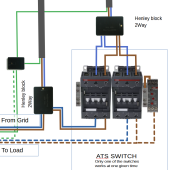
I made my ATS from ABB contactors, not cheap, but it is something certified
its AF52-30-00 with a mechanical interlock and 2 NC/NO blocks and 1 timer(ABB CT-MFE)
It's not chinesium grade
These are rated up to 100Amp AC 600V(single phase)

1683723074793.png
 
It would be interesting to see how my Victron Multiplus reacts if I was on shore power and then kicked on the generator. I don't have the equipment to watch the AC quality, so all I could look for was smoke coming out of the devices or something shutting down.
Depending on the luck of the draw on AC input phase difference, it may pop AC input breaker, damage pass-through relay contacts, cause inverter to shut down, or even blow out inverter. If you happen to flip the transfer between two live AC inputs when their phase is 180 degrees out of sync it is the worst case surge current.

Going from generator to grid is worse because grid is usually capable of providing higher surge current.

You have to make sure the inverter's pass-through relay releases before applying another AC input source.
 
Last edited:
Depending on the luck of the draw on AC input phase difference, it may pop AC input breaker, damage pass-through relay contacts, or even blow out inverter. If you happen to flip the transfer between two live AC inputs when their phase is 180 degrees out of sync it is the worst case surge current.

So it's probably not a good idea? LOL. Yeah, I'm not going to do that.
 
So it's probably not a good idea? LOL. Yeah, I'm not going to do that.
I considered that, i have 2 Inverters which have to sync, which means just in case, post AC output of both inverters you need overvoltage protection
Something like https://uk.rs-online.com/web/p/surge-protection-devices/7125272
This is for 250v(so UK/europe)
Or using the system like i have above:
Using a relay that checks for over voltage, triggers the contactor and disconnects the panels and back to grid input
 
Last edited:

diy solar

diy solar
Back
Top