diy solar

diy solar

Growatt EPS connection

timray13

New Member
Joined
Oct 10, 2022
Messages
7
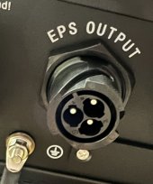
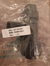
I have a Growatt SP5000H inverter with 9kW battery storage and in anticipation of winter power cuts I would like to connect a double socket to the EPS output. I have the 3-pin connector but there are no polarity markings on it. Does any one know which is LNE - have searched Growatt docs but they say connector should be marked. Thanks is advance.
 
Hi Timray13,
You said you have the 3 pin plug which is something I’m trying to find and buy. The photo I’ve attached is from my SPH6000. If you look closely, you can see the physical ports are marked L, N and E. I assume you can simply align with the plug as there is a key slot to prevent you plugging in anyway but correct? Do you have any make or reference numbers on the plug please?
Regards Simtomo.
 

Attachments

  • 2A224DF6-29BB-4961-8A67-87399271A1D1.jpeg
    2A224DF6-29BB-4961-8A67-87399271A1D1.jpeg
    262.1 KB · Views: 29
Hi Timray13,
You said you have the 3 pin plug which is something I’m trying to find and buy. The photo I’ve attached is from my SPH6000. If you look closely, you can see the physical ports are marked L, N and E. I assume you can simply align with the plug as there is a key slot to prevent you plugging in anyway but correct? Do you have any make or reference numbers on the plug please?
Regards Simtomo.
Thanks for the reply I have found the labelling on the connector - it is VERY small. I can't find any reference on the connector but I found mine in the box which the inverter came in along with the documentation so if you still have the box check it out. If not, you could try your local Growatt support - they were helpful - service.uk@growatt.com for uk support. Good luck.

PS haven't had a chance to test the EPS output but have wired it to a 4-way extension block with individually switched sockets and two USB ports for emergencies. Fingers crossed.
 
Thanks Timray13, I suspected as much on the connector. Glad you sorted your wiring out, I intend to do the same. We should have up to 3kW, assuming the battery has some capacity if the grid gets turned off.
Regards Simtomo.
 
Thanks Timray13, I suspected as much on the connector. Glad you sorted your wiring out, I intend to do the same. We should have up to 3kW, assuming the battery has some capacity if the grid gets turned off.
Regards Simtomo.
Tried it out today and it works as it should. As soon as the power went off, the EPS output became active. Should be really helpful if we get winter power cuts.
 
Tried it out today and it works as it should. As soon as the power went off, the EPS output became active. Should be really helpful if we get winter power cuts.
I tried a couple of evenings ago but couldn't get the eps to work. Do you unplug the AC connector as it says the AC and EPS should not be used together or just turn the AC off at the isolator switch? Trying to see why it doesn't work for me...
 
I tried a couple of evenings ago but couldn't get the eps to work. Do you unplug the AC connector as it says the AC and EPS should not be used together or just turn the AC off at the isolator switch? Trying to see why it doesn't work for me...
I switched off the AC isolator to the inverter and the EPS became active immediately. Then tried switching off the main switch on the distribution board and it worked fine. as far as I can tell it should just work.
 
I just remembered that in the setup of the inverter there is an EPS On/Off setting - mine was already set to ON. Worth checking.
 
Hi, if I may jump on this thread. I'm also hoping to enable EPS on my system. I've noticed the EPS works intermittently for me. E.g. as a test, with nothing yet connected to EPS connector, I just remove grid ac and monitor the EPS menu. First attempt it shows EPS 230v & no load, all good ? Second attempt later in day, same test but no EPS output ? . Battery on both occasions above 50 percent. I've tried this repeatedly now and always get these random results. Has anyone else witnessed this. Also noticed when EPS voltage is present I see a small overload symbol, yet no load connected? ☹️
 
It may be because you have no load on the eps output, I wired in a 4 way switched extension lead and it seems to work. Have plugged in chargers and lights, etc.
 
My installer did not leave the EPS socket for my Growatt inverter. Has anyone managed to obtain one of these and if so where from? Thanks
 
I managed to get my installer to leave the EPS connector with me. The part is a 'Vaconn Power VPAC06EW-3P(SC)8'.

The LNE is moulded into the mating end of the connector, and as described previously is very small. I would strongly recommend some careful testing with a test-meter before connecting any equipment up.

One thing I have noticed is that when grid power is restored, the inverter takes a long time before battery charging is resumed.

The Growatt ATS-S is available but I could find nowhere with stock, so I am putting my own design together with a couple of contactors and a couple delay-on timers.
 
My installer did not leave the EPS socket for my Growatt inverter. Has anyone managed to obtain one of these and if so where from? Thanks
Mine did not either and will not let me have it as they want to charge for the EPS connection and cable - apparently they have loads of them as they remove them from the box before installation. I am going to try and find the connector Steve W mentioned - if you find it can you let me know - thanks
 
When I measure the EPS output, I get the following AC volts readings: Earth & Neutral = 114v, Live & Neutral = 231v and Earth & Live = 117v, they should read when measuring with a test instrument: Earth & Neutral = Continuity, Live & Neutral = +/- 230v and Earth & Live = +/- 230v.

These are insufficient to trip 30mA RCDs which are a requirement with sockets, I am reluctant to connect any load to the EPS knowing that any faults would not trip the RCDs - Have you come across this problem and how did you get round it?
I think that is common for many EPS outputs or generators working in backup or "island mode".

The RCD should trip if there's an imbalance between line and neutral, whatever the potential of the earth connection.

But because the earth from the DNO cannot be relied on during a grid outage, the earth is left floating, but can be (and should be) linked to a local earth rod.

Q for those who linked up thir EPS outputs: Do you have a local earth rod?

If you don't have have an additional earth then using other than standalone devices on the EPS may still lead to voltage arrising between the floating earth and mother earth via say HDMI, ethernet cables or other paths via equipment linked signal wiring.

A properly confgured EESS (Electrical Energy Storage System) should link earth and neutral on the backup (EPS) supply when they fail over in to island mode. (Also there must be iusolation from the grid, whiuch can be automatic or via by using a dedicated output.)

As well as BS7671 the MCS rules specify that the RCDs should still work even in island mode.


These links explain a bit more


I appear to have been left mine. Also discovered last night when the grid went out that EPS was a thing, and one not setup on the system in the house I just bought. Photo of the package attached for those trying to source one.

Had a power cut last night and I keep medication in the fridge which would have been good to have kept running of an EPS socket and also keep my phone charged which monitors medical sensors for me and alerts me to issues.

Am I correct in thinking I just need to pull the plug off a 4 gang extension, wire it to this so live to live etc and then in the event of a future outage the sockets will go live and I can run up to 3kW of load for as long as the battery lasts? When the grid comes back the sockets go dark again though.

Also I don't seem to have generated anything from the PV system today, when in EPS mode I'm guessing it stops power generation incase it has no where to put it?
 

Attachments

  • 20240122_181806.jpg
    20240122_181806.jpg
    95.3 KB · Views: 6

diy solar

diy solar
Back
Top