Hello,
I'm building a 4S battery pack with CALB cells and a smart JBD 4S BMS board.
I received the cells as grade A ( new), all showed the same voltage level of about 3,2 Volts.
I'm currently in a working stage to lab' test the components and functions, battery and BMS.
To condition the cells I have parallel connected them as received and charged them up to 3,65V and let them rest for a minimum of 24 hours in connected condition.
As the next step I series connected the cells and conducted a capacity test 0,5C load, test confirmed 206 AH's capacity, and charged the pack again until it reached the max charge level of 14.5 Volts. The BMS cut off the charging process when the first cell reached 3.65 V OVP .
It became obvious while charging that one cell showed a higher voltage level from about 3,4 ave volts per cell onwards.
After charging I parallel connected the cells again and let them rest and zip balance for at least 24 hours, than I parallel connected the pack again with the BMS in place.
I conducted some moderate discharge and charging action to watch the voltage levels.
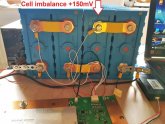
My observation is that one cell is alway ahead the three other cells of a minimum of 150mV.
The other 3 cells voltages are tight together.
This results that this one particular cell reaches the OVP at first (3,65V) and shuts off the charging process.
BMS balancer kicks in as expected at 50mV diff., balance turn on voltage at 3,4 V, however, not able to equalise the diff voltages in a timely manner.
I'm looking for your comments based on your experience if there is anything wrong in the initial balancing process or recommendations I could do to improve the voltage drift situation.
BTY: What is the voltage drift you see on your set ups and what are acceptable limits ?
Have a nice day,
Waldemar
I'm building a 4S battery pack with CALB cells and a smart JBD 4S BMS board.
I received the cells as grade A ( new), all showed the same voltage level of about 3,2 Volts.
I'm currently in a working stage to lab' test the components and functions, battery and BMS.
To condition the cells I have parallel connected them as received and charged them up to 3,65V and let them rest for a minimum of 24 hours in connected condition.
As the next step I series connected the cells and conducted a capacity test 0,5C load, test confirmed 206 AH's capacity, and charged the pack again until it reached the max charge level of 14.5 Volts. The BMS cut off the charging process when the first cell reached 3.65 V OVP .
It became obvious while charging that one cell showed a higher voltage level from about 3,4 ave volts per cell onwards.
After charging I parallel connected the cells again and let them rest and zip balance for at least 24 hours, than I parallel connected the pack again with the BMS in place.
I conducted some moderate discharge and charging action to watch the voltage levels.
My observation is that one cell is alway ahead the three other cells of a minimum of 150mV.
The other 3 cells voltages are tight together.
This results that this one particular cell reaches the OVP at first (3,65V) and shuts off the charging process.
BMS balancer kicks in as expected at 50mV diff., balance turn on voltage at 3,4 V, however, not able to equalise the diff voltages in a timely manner.
I'm looking for your comments based on your experience if there is anything wrong in the initial balancing process or recommendations I could do to improve the voltage drift situation.
BTY: What is the voltage drift you see on your set ups and what are acceptable limits ?
Have a nice day,
Waldemar