diy solar

diy solar

low budget offgrid project

perryfranz

New Member
Joined
Aug 31, 2022
Messages
39
Hi everyone!
I'm building my first offgrid system here in Italy trying to mantain at the lowest all the cost without sacrifice security and quality overall.

What I have:
- 4 jinko solar JKM240P-60 240W (55€ -54$ each)
- 1 EPever MPPT XTRA4415N (200€ - 197$)

What I have to buy:
- 24V 3500W Edecoa inverter (~390€ - 384$)
- 24V 280Ah DIY battery+BMS (in evaluation)
- Test equipement to test the cell (to be defined)

Define the context :
in my house I have already an ongrid 3Kw sistem without battery (legally I cannot touch the system or modify it, I have to do many paper and spend lot of time to do it... Italian burocracy...) but with the electricity cost increasing now it's pricy charging my "125cc" electric scooter that I use to ride home-work and I need to charge it up every 3-4 days (it takes 3kWh), not so much but I can only charge it during night paying 4 times the price for kWh that Enel (the Italian power distributor) pays me for 1kWh sent ongrid (I pay 0.4-0.5kWh and they pay me 0.1kWh circa).
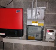
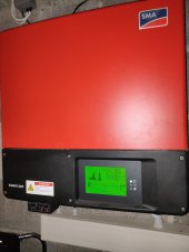
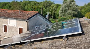
This is my existing system: 12 panel 250W Solarworld, SMA Sunny Boy 3000LT-21.
IMG20220808082435.jpgIMG20221023113025.jpgIMG20221023113034.jpg
Today is really cloudy here... so not so much free energy! this system was installed in 2016, the picture of the solar panel is from August when we washed them after several month without rain.

Using the offgrid system only for the scooter is quite pricy and useless, instead I want to use this system to power up when needed also our Miele washing machine (boiling cotton 60°C takes around 1.5kWh) or the AC minisplit inverter to heat up the house instead of using the naphtha furnace/boiler primarily (in the countryside is still common or LPG furnace/boiler) because in winter we obviously have less sun hour and when the sun goes down my ongrid system is useless (typically after 4-5pm).

Last but not least in countryside we do not have aqueduct, so the only way to have water (drinkable obv) is via autoclave, if there is a power outage we have an Honda eu22i to power it up but it's not convinient to use, so in case of emergency I can use the offgrid system (the Inverter marked above have surge power of 7kW, the installed DAB Jet 132M have Pmax/surge: 1,5kW and Pn aroud 1.3kW mesured).
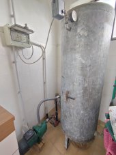
IMG20221023114924.jpg

What I want to do:
I want to build up the system on the shed roof (50m^2 / 538sqf) that is near the garages, laundry, AC and autoclave; all the battery/inverter/mppt installed in a dedicated space inside the garage that I can isolate better for winter/summer cilmate.
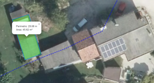
1663345121501 (2).png the blue line marks a landscape constraint, so I can not use my roof below the blue line (southeast) without many permission.

I want that this system can be upgraded easly by the year adding more used solar panel and more diy battery in the future (that's why i choose separated MPPT-inverter instead of a All In One solution).
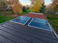
The 4 solar panel are going to be plugged in 2s2p and installed flat on the metal roof surface (less expensive) so I can add 4 more panel 2s2p to reach maximum value of the MPPT before I need to buy another one.

Problem:
My biggest problem is the diy battery, I'm sure about the 8S EVE LF280K and the Jk B2A8S20P-HEAT BMS (because here is common -0°C/32F inside the garage and I really like the integrated feature.
But before concerning about how I can install the heating element/enclousure/... I have to deal with the dealer choice: I prefer buying from dealer on Alibaba that has an european warehouse so I can de more calm about DDP, shipping time and etc.
I'm following the thread about GradeB EVE but for my needs I don't think that a GradeA battery can be really a must have, I obv want the same capacity as payed and the same internal resistance as possible... but what do you think? .

I will update this thread about the installations for this project, but if for you I can do something better/different let me know! I'm here to share an learn :)

Francesco
 
Last edited:
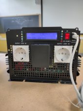
I'll give you advice to change your mind about the Edecoa inverter. It likely is one of the Chinese inverters that do not have grounding capability or the grounding is poor. If you plan connect one/two devices to it directly, without spreading the electricity from this inverter to a set of devices - then ok, it may be fine. If you do, however, plan use the inverted to power set of devices through power leads then lack of proper grounding may create a risk to your safety :/ Been on this myself and have not found a good solution yet - how to apply safety via proper grounding to such a cheap Chinese inverter.

Some devices may require grounding in place - check the journey Andy from Off-Grid Garage went through trying charge his Tesla ->

With my comment, having a 2kw Edecoa, I want point need to consider safety of the system you're planning.
 
Last edited:
Thank you, but it seems not a problem here in Italy in general, because we have every single socket grounded and protected with gfci ( we do not call with that name but "differential" that switch off the system when it detects more than 30mA to ground) so we do not have this type of problem like in Andy's video. I learned this thing also in electroboom videos.
So, my plan is to connect the inverter to a line protection but using the existing ground connection of the house, so I can put upstream the differential, than using some magnetothermic upstream every single socket according to the max power required (16A for the washingmachine and AC, 10A for my scooter charger [850W 230V] and autoclave) because I will not use multiple device at the same time; so I can be protected in both ways, but here in Italy it's a must have by law otherwise, if it is not present everywhere, authorization to connect to the grid is not given, and also you must have the system certified by an electrician even if it is offgrid and DIY.
Obv I have also to use suitable conductor size for the power in use.

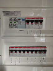
This is my house's main panel, you can see two high voltage arresters, the differenzial magnetothermic upstream many magnetothermic switch that which disconnect the electrical system in many part, like "L giorno-light living area" "L notte- light bedroom" "FM caldaia- driving force furnace/boiler" " FM cucina- driving force kitchen" "FM lavatrice- driving force washingmachine"... so the intire house is ground protected as I want to do in the Offgrid system, but I desire also to add some fuses because they are quickier than magnetothermic and cheaper, but I have to define the detail with my collegue in High school that teach electrical engineering system instead of electrical engineering theory like me, they know much better which switch goes where.
IMG20221025145159.jpg
 
Just bought:
- bms -> JK B2A8S20P-Heat
- test equipment -> Yaorea YR1035 and Atorch DL24EW (in cart I have also the splicing for more 150W, maybe next order).

I still have to define where to buy the raw cells: Docan or Dongguan Lightning or other alibaba store that have EU warehouse.
 
but it seems not a problem here in Italy in general, because we have every single socket grounded and protected with gfci
I did not think about your existing grid protection, I was referring to how you plan protect electricity created by the inverter - off-grid electricity. The grid is secured with the residual current circuit breakers because grid is designed to provide grounding and when there's leak to ground (through your body or a device case), the breakers can detect difference in current flow on Live and Neutral, and cut off flow of current. When an inverter is not connected to ground, and the Chinese have problem with this, you can't just add residual current circuit breaker to it - it won't work, current won't flow to ground but through body to inverter - because ground (earth) is not capable receive current from inverter. Andy was showing problem with Tesla charger not detecting grounding - the cheap Chinese inverters are not designed to respect the grounding of ground. What Andy pointed at the end of his video, the Chinese inverter he has was leaking AC output onto DC input with his grounding solution - to the battery. The inverters are not designed to support house main or act like one, what Chinese manufacturers explain indirectly by providing in manual of their inverters that you should always connect devices directly and not through extension leads as the inverters are not designed for this.

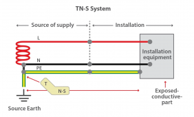
There are different earthing systems but let's look on TN-S:

1666993121519.png


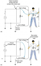
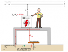
By design, grounding is connected to neutral of a grid (outside your house) and current flows between live and neutral. Residual current circuit breakers sit on the live and neutral lines and "monitor" whether the same current flows on red and black lines. If it happens that a connected device breaks and circuit is intercepted by human's body or case of the device, current may flow through body or case of the device to ground - creating difference of current flowing on L and N lines, which are monitored by circuit breaker - triggering it to cut off flow. If a device's case is connected to neutral, current won't go through body and breaker may switch:

1666993858230.png


Without possibility to make grounding for an off-grid inverter (and Andy's Chinese had a "grounding"), if you'll break circuit - current will flow through something (maybe your body) and will want go back to the inverter - it won't go to ground as there's no ground like on the picture, presenting the TN-S system.


Maybe, it is not a problem for you, in your scenario (not sure), but wanted to point that use of circuit breakers in an off-grid solution, without possibility to ground inverter, is impossible by design.
 
Last edited:
@jimjoe that's intresting, let's talk about it.
In US there is the TN-C or TN-S system, here in Italy we have the TT system, it means that:
the electrical system is powered directly in low voltage by the supplier company. This is what happens inside private homes here in Italy (usually 230V single-phase) the neutral conductor is considered active in every respects and, as such, must be sectionable. In a TT system, the earthing system of the supplier's substation that transforms the medium voltage into low voltage is different from the earthing system of the powered building.
1667319429115.png

This is regulated from 1990 law and upgraded with DM37/08 art.6 comma3.
With the TT system we want to create an "ring of failure" using for the failure current IDN also an "dirty ground resistance" RA that it can be also high (like 100Ohm), that's why we use the differential switch.
1667319978343.png
1667322454380.png
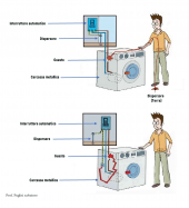
as "interruttrore automatico" -> differential
"dispersore" -> grounding
"guasto" -> failure
"carcassa metallica" -> metal case

So, let me use some picture from the slides that I use in my class, there are some part in Italian that I can translate quickly:
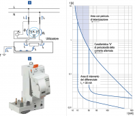
1667320310480.png "utilizzatore" -> load
we can see that we have L,N (phase, neutral) connected via differential switch to a generic load, when failure occours (active condutor to washing machine case) the case is grounded and the current flows to earth, so we have Id=30mA (current I - d differential) maximum that trigger the switch to open the circuit to load. This appen to every external conduction that are not L,N (yourself, the dog, water inlet, ...).

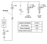
So, let's use a generic scheme only with light (illuminazione, max 10A) and socket (prese, max 16A) at 230V single phase: 1667320733663.png
we can see that upstream everything we have a power source indefinied (gas generator, inverter, grid, magic, idk,..) that provide 230V AC, we have the Wh meter (picture of a ongrid system), a 25A thermal breaker (usually inside the meter in Italy) and another thermal breaker (usually the one that you put inside the switchboard as redundancy). Before every single load (or section like lights, sockets, bathroom, laundry room, garage, washing machine,...) you have always a dedicated thermal breaker and differential switch (usually combined), so in case I touch one of that old fancy metal lampshades with one conductor touching the metal pole (and the lamp is on top of a glass table) when I touch with bare hand and wet feet the metal pole, the differential switch open the circuit when the current is at 30mA (value obtained as the difference between incoming and outgoing current) that can save my life, that's why the Italian company BTicino named the differential as commercial name with "salvavita" that is life-saving... so it's usual to see old people screaming "è saltato il salvavita!!!" - "the lifesaver is blown!!!" and not "the differential the switch has opened the circuit" :ROFLMAO: .


So, for me there is no safety problem with direct or indirect contact with the load, that's a different scenario if we have this kind of fault inside the inverter or the MPPT but we have such a low voltage that I do not think that it's hazardous.

So, in theory, if I understood what you said I do not have this kind of problem.
I hope that I understand your post and that is understandable my answer :)
 
Last edited:
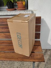
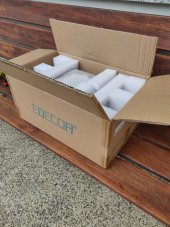
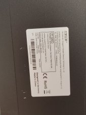
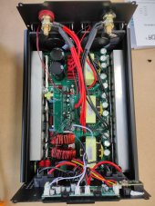
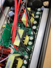
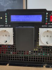
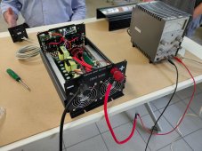
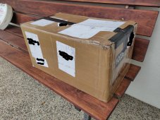
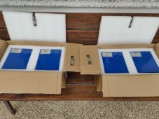
Arrived the Edecoa DPP35 (sinemate 3-352D) bought from aliexpress and shipped from DE with a great deal than Amazon.it (from 400€ to 338€).
I took it to school to show it to my students and collegue, we all appreciated it; well built for this price!
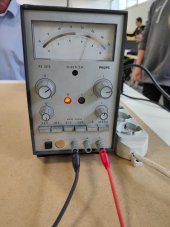
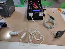
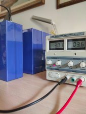
I tested it with power supply and it worked just fine, from the low voltage indicator to power consumption etc.. Here's some picture from shipping box to test :)

IMG20221102124438.jpgIMG20221102141400.jpgIMG20221102141627.jpgIMG20221103115502.jpgIMG20221103115509.jpgIMG20221103124434.jpgIMG20221103124437.jpgIMG20221103124446.jpgIMG20221103124450.jpgIMG20221103124635.jpg
 
Hi everyone, I didn't update anything due high school meeting and exams.
Here we are, I just recived evrithing:
- BMS JK-B2A8S20P-H (heat function)
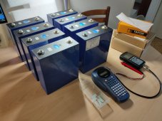
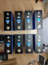
- 8 EVE LF280K from Dongguan Lightning ordered from EU warehouse via Rain Zeng that was super communicative and he followed me on every aspect (he constantly followed the shipment, also updating me on a delay (purchased on 10/28/2022 and received on 11/16/2022, at the time of purchase they were out of stock).
Here's some picture of the shipping and cells:

IMG20221116124124.jpg IMG20221116134558.jpg IMG20221116145112.jpgIMG20221116145131.jpg

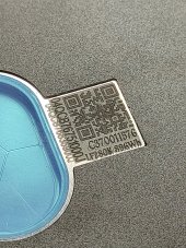
All the cells have the QR code was scratched and "reprinted" you can see the "B" underneath, with patiend I can try to read all the scrathed original code, like here that is obvious

IMG20221116152340.jpg


neither cell is swollen or damaged evidently, ony one has one dent on the side (curiously is circled...) as you can see here:
Screenshot_2022-11-16-14-13-10-90_99c04817c0de5652397fc8b56c3b3817.jpg

I will test the cells later today with the YAOREA YR1035+, I label them all and catalogue in excel with V and mΩ (next days also with Ah with the Atorch DL24EW 150W)
 
Hi!
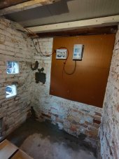
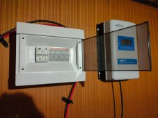
yesterday I installed the panels (which must be fixed to the roof of the woodshed), I proceeded to install the MPPT and organize the spaces.
The panels were installed 2S2P.
Late this afternoon I thought I'd finish assembling the panel in DC.
What do you think?
WhatsApp Image 2022-11-20 at 16.30.41.jpegWhatsApp Image 2022-11-20 at 16.30.42.jpegWhatsApp Image 2022-11-20 at 16.30.43.jpeg
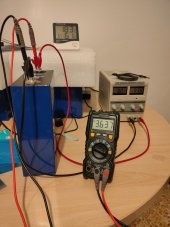
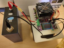
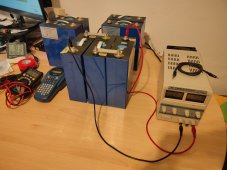
Now i'm top balancing the first cell, so I can discharge them with the DL24EW. 3A is the max current that my generator can pull out, this cell was at 3.31V and this morning the cell was at 3.37V..... it will be very slow...
WhatsApp Image 2022-11-21 at 12.56.31.jpeg
 
Just charged the first cell and ready to run the capacity test with the DL24EW at 10A (first time, better slow and monitored).
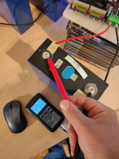
I have attached the ntc sensor to the cable so I can monitor how the 12AWG-4mm^2 original cable manage costant 10A (in the worst scenario it will cutoff the test over 100°C and the cable is claimed for 105°C) I do not thing that this cell can heat up at low current
 

Attachments

  • IMG20221122151615.jpg
    IMG20221122151615.jpg
    137.6 KB · Views: 8
  • IMG20221122153730.jpg
    IMG20221122153730.jpg
    211.9 KB · Views: 12
  • IMG20221122153738.jpg
    IMG20221122153738.jpg
    129 KB · Views: 9
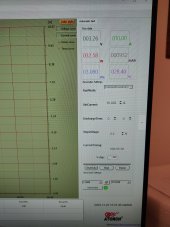
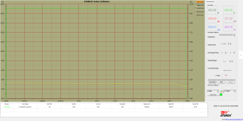
First test done!
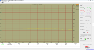
marvellous! the ambiguous cell pulled out 289Ah and 904Wh!
1.png
The DL24EW worked perfectly for over 30h but the software crashed when I tried to save the curve, fortunatly the pc's was running fine and let me screenshot, maybe the software do not like W11.
Now I'm waiting the other cells to charge before running the test again for 7 times and than again charging them up before assembly.
IMG20221124164754.jpg
 
"Houston we have a problem"
I'm testing battery number 4 (in the picture above is the one charging on the left), it was charged perfectly but the voltage under load drops too fast, not like the other one I have tested before).

IMG20221125153118.jpg

here you can see the video
 
the test ended mid-morning with a warning "less than stop voltage" because the battery dropped too fast under load and the instrument didn't have the time to stop just in time.
The battery pulled out 278.43Ah and 860Wh but as you can see in picture, it has a strange curve 2.png
What do you think guys?

Now I'm testing battery n°3 and waiting the end of charge of battery n°2... yes, i didn't follow my order of labeling :ROFLMAO:
 
Last edited:
Back
Top