diy solar

diy solar

Pass thru current in the case of a catastrophic inverter failure

kuRi0us@bt

New Member
Joined
Jul 17, 2024
Messages
5
Location
Puerto Rico
In a Grid tied system with a Hybrid inverter is there any possibility of my home remaining without grid power in the case of a failure of the inverter?
The reason I ask this is because hybrid inverters have a "pass through current rating" for power coming from the grid but I have no clue how this circuit works internally. If there is any circuitry at all involved in allowing this current to flow, then theoretically there is a chance that it can fail and therefore leave me with no power until the inverter is replaced.
This is a major concern for me because I live in P.R. where power is notoriously unstable, hurricanes are an issue, and equipment needs to be shipped overseas or flown in (one takes forever and the other can be very costly). If this possibility exists, then I would have to try and design my system with some sort of bypass between the grid and the inverter in order to have power while the equipment can be replaced.
Thanks for any and all feedback.
 
You may want to use a transfer switch external to the inverter. If the inverter fails (as in the case of Sol-Arks) it will not pass through the grid power. If you can shutoff power at the meter, then a quick rewiring could be a cheaper solution.
 
You may want to use a transfer switch external to the inverter. If the inverter fails (as in the case of Sol-Arks) it will not pass through the grid power. If you can shutoff power at the meter, then a quick rewiring could be a cheaper solution.
Quick rewiring would definitely be cheaper, but it's not always feasible for us. This might come as a surprise to some, but our houses are almost all made of concrete and concrete block. Wiring is done in conduits inside the walls, so re-wiring can be... complicated. I have analyzed the transfer switch option but i'm not sure how that would work, yet.
Thanks.
 
Oof. I'm a total NewB here so i'm struggling to follow that thread. The diagrams are hard to read as well.
Thanks.

The basic flow that many people install is grid power (power meter) > solark 15k > main breaker panel. The discussion in the thread is to add a transfer switch between the grid power (power meter) and solark so power can be sent directly to your main breaker panel in the event of an inverter failure.
 
Quick rewiring would definitely be cheaper, but it's not always feasible for us. This might come as a surprise to some, but our houses are almost all made of concrete and concrete block. Wiring is done in conduits inside the walls, so re-wiring can be... complicated. I have analyzed the transfer switch option but i'm not sure how that would work, yet.
Thanks.
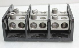
Many ways to skin a cat, but do you have access to wires going into your inverter? If so, then distributor blocks with a quick wire change would work if inverter fails (highly recommended shutting off grid power first). Could have “bypass” wires precut for quick changeover.

Examples:
 

Attachments

  • IMG_3054.jpeg
    IMG_3054.jpeg
    160.7 KB · Views: 2
  • IMG_1020.jpeg
    IMG_1020.jpeg
    222.3 KB · Views: 2
Many ways to skin a cat, but do you have access to wires going into your inverter? If so, then distributor blocks with a quick wire change would work if inverter fails (highly recommended shutting off grid power first). Could have “bypass” wires precut for quick changeover.

Examples:
I don't have an inverter, or a system, yet. I'm in the planning phase and trying to consider all of my options before pulling the trigger.
Precutting bypass wires might end up being a good option if the transfer switch route turns out to be too expensive or otherwise not doable.
PLEASE don't judge me, remember that i'm very green at this, but I have attached a schematic diagram of my planned system so far. I know that it's far from correct or final, but it kind of illustrates my doubt with the transfer switch.
Power goes in from the grid to the xfer and out, either to the inverter's grid feed or, to the distribution panel, but then i also have power coming from the load side of the inverter to the distribution panel. I don't think i can just feed two inputs onto my distribution panel, that doesn't make sense to me. On the diagram I added a second manual transfer switch to convert the two possible inputs to one in the panel, but that doesn't make sense to me either!
I'm lost on how that would actually be done.
 

Attachments

  • 0000 MY DIAGRAM TEST - MANUAL xfer sw.pdf
    443.6 KB · Views: 4
I think I found my answer on the EG4 Manual posted on the Thread that SolarFlares pointed to.
Does the attached diagram bypass the Inverter when the transfer switch is set to the bottom "on" position, or does it still somehow need to pass through the inverter to power the loads?
 

Attachments

  • Page from EG4-18KPV-12LV-Manual-1.png
    Page from EG4-18KPV-12LV-Manual-1.png
    626.1 KB · Views: 2

diy solar

diy solar
Back
Top