offgridandy
New Member
Hi all and thank you for your welcome.
As I mentioned I have recently obtained a near new EV battery. Done only 1000 miles on a 2022 build date, so perhaps been charged 6 times.
The battery as built for Peugeot is as follows.
51 KWh.
Pack voltage 400V
Capacity 127.5Ah.
Total cells 216
Battery pack 108s2p
Modules 18
Module energy 2.74kWh
Module nominal 22V
Cells in module 12
Module configuration 6s2p
Format Prismatic.
Cell chemistry Lithium ion NMC
Cell nominal Voltage 3.7V
Standard charge and discharge cut off V 4.2V/2.75.
Cell capacity 62Ah
Battery voltage before dismantling was 388VDC and individual cells measure 3.59V
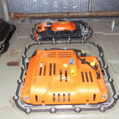
The battery as a whole is or was water cooled.
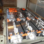
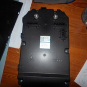
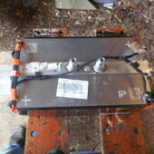
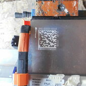
So, I have separated the 2 halves of the metal case and dismantled the battery down to packs/ modules.
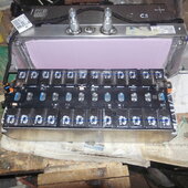
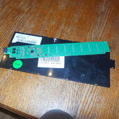
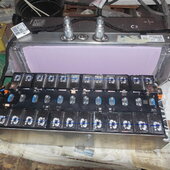
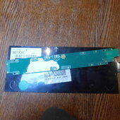
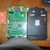
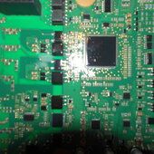
Then I have partially, non, destructively, dismantled one module. Very careful removal of one module cover exposed the top of the cells. Installed across the top of the 6s2p cells is a circuit board. This is an interference fit onto a number of small pins on the top of the cells. With the circuit board removed one can see that the string has welded bus bars.
My basic plan is to upgrade my off grid power system from 24V to nominal 48V.
I am a long time user of Outback equipment, for it’s rugged build and reliability and simplicity and would wish to use their brand of inverter charger for the upgrade as I am familiar with their programming and menus etc.
The spec of the Outback VFXR3048E allows for DC charging on a scale from 42 to 68VDC. To support a larger load in the house I would have 2 inverters in parallel which also enables battery charging at a higher rate from a gen set (2X 45ADC).
2 of my modules in a series pack will connect to give a nominal 44V battery. So I could have 9 packs at 44V in parallel. If I have a low volt point for recharge set at 43.2 (3.6V per cell) (30%SOC) and top V for charging at 49.2 (4.1V per cell) then that fits in with the Outback VDC capability.
My first question is how best to use the modules.
If I could just use the 44v battery as indicated above would the circuit board (BMS) be useable or would I need to strip all the boards of the individual modules and replace.
If the circuit boards can stay then what else will I need as regards battery management? I don’t mind spending money but I only want to do things once. I also don’t spend my life constantly tinkering and resetting stuff. I need a system that will reliably power my house without switching itself off on a whim.
All ideas welcomed but go easy on me as I am new to the tech and also quite old and grey; but still learning, just slower. Remember I have 25 yrs experience driving a 24Kwh FLA battery and zero experience of Li ion.
As I mentioned I have recently obtained a near new EV battery. Done only 1000 miles on a 2022 build date, so perhaps been charged 6 times.
The battery as built for Peugeot is as follows.
51 KWh.
Pack voltage 400V
Capacity 127.5Ah.
Total cells 216
Battery pack 108s2p
Modules 18
Module energy 2.74kWh
Module nominal 22V
Cells in module 12
Module configuration 6s2p
Format Prismatic.
Cell chemistry Lithium ion NMC
Cell nominal Voltage 3.7V
Standard charge and discharge cut off V 4.2V/2.75.
Cell capacity 62Ah
Battery voltage before dismantling was 388VDC and individual cells measure 3.59V
The battery as a whole is or was water cooled.
So, I have separated the 2 halves of the metal case and dismantled the battery down to packs/ modules.
Then I have partially, non, destructively, dismantled one module. Very careful removal of one module cover exposed the top of the cells. Installed across the top of the 6s2p cells is a circuit board. This is an interference fit onto a number of small pins on the top of the cells. With the circuit board removed one can see that the string has welded bus bars.
My basic plan is to upgrade my off grid power system from 24V to nominal 48V.
I am a long time user of Outback equipment, for it’s rugged build and reliability and simplicity and would wish to use their brand of inverter charger for the upgrade as I am familiar with their programming and menus etc.
The spec of the Outback VFXR3048E allows for DC charging on a scale from 42 to 68VDC. To support a larger load in the house I would have 2 inverters in parallel which also enables battery charging at a higher rate from a gen set (2X 45ADC).
2 of my modules in a series pack will connect to give a nominal 44V battery. So I could have 9 packs at 44V in parallel. If I have a low volt point for recharge set at 43.2 (3.6V per cell) (30%SOC) and top V for charging at 49.2 (4.1V per cell) then that fits in with the Outback VDC capability.
My first question is how best to use the modules.
If I could just use the 44v battery as indicated above would the circuit board (BMS) be useable or would I need to strip all the boards of the individual modules and replace.
If the circuit boards can stay then what else will I need as regards battery management? I don’t mind spending money but I only want to do things once. I also don’t spend my life constantly tinkering and resetting stuff. I need a system that will reliably power my house without switching itself off on a whim.
All ideas welcomed but go easy on me as I am new to the tech and also quite old and grey; but still learning, just slower. Remember I have 25 yrs experience driving a 24Kwh FLA battery and zero experience of Li ion.